


Multiport Testing with CMT VNAs & Off-the-shelf RF Switches
April 19, 2018Introduction
Copper Mountain Technologies offers VNA with one port, two ports, or four ports. But sometimes, more ports are required, for example for testing multi-port devices. There are many options to achieve multi-port measurements, such as manually connecting and disconnecting each port, or using an OEM switch matrix system. Manual re-connection can be time-consuming to the point of being impractical, depending on the test requirements; on the other hand, test equipment vendors’ switch systems are relatively expensive especially, considering these are often repackaged versions of commercially available switches.
Another other option is to use an off-the-shelf RF switch to achieve a higher test port count than the VNA contains natively.
This application note describes the approach of using off-the-shelf RF switches to achieve multiport measurements, some discussion of considerations when selecting such a switch, and a sample of test results from a specific experiment involving an RF switch.
Pros and Cons
First, let’s look at the advantages and disadvantages of using an off-the-shelf RF switch for port expansion.
The advantages of using an off-the-shelf RF switch are:
- Lower cost relative to test equipment vendor-provided or custom integrated switch matrices
- Simplified and higher speed measurement process compared to manual re-connection
- Full automation can be achieved by programming
- A very large number of ports can be obtained, limited only by the specifications of the switches selected
- Higher performance than daisy-chaining PXIe modular analyzers to achieve high port count
And there are some disadvantages as well:
- Loss and mismatch are introduced in the system, which must be accounted for in any switch selection and test system design process
- Calibration complexity is increased, relative to an unswitched test scenario
- Automation of the switch itself requires a degree of programming effort during the integration process
Choosing a suitable off-the-shelf switch
There are many kinds of RF switches for intended various purposes. Differences among them include number of ports, different types of switching mechanisms, and different performance characteristics. Many specifications need to be considered to match your application, such as the number of output ports, operational frequency range, and switching speed of the switch.
And especially, RF performance factors need to be considered to ensure sufficient accuracy of your RF measurements.
Electromechanical versus Solid State
There are two major switch types, electromechanical switch and solid state switch. The advantages of the solid-state switch are low noise, long product life, and higher switching speed. The advantages of electromechanical switches include low insertion loss and better input and output impedance matching. Therefore, in general, electromechanical switches are the recommended switch type due to its superior RF performance, except when switching speed is paramount.
There are several specific characteristics related to the RF switch performance including internal termination, isolation, insertion loss and VSWR. Although some of these limitations can be offset through proper calibration, a better quality of switch can still increase the accuracy of your measurements.
RF Performance: Internal termination
Regardless of the switch technology selected, internal termination is necessary for good RF measurements. Internally terminated switches, also commonly referred to as absorptive switches, present a 50 Ohm load to all unused ports. This configuration is necessary to minimize reflections from un-measured ports, just as would be the case were a multi-port VNA were used for the measurement. If a switch is not internal terminated, commonly called a reflective switch, the unconnected ports will be open and this is not typically acceptable.
RF Performance: Isolation
Isolation of a switch refers to the power level measured at an unused output connector referenced to the power at the input connector. Better Isolation leaves unconnected ports in a better-loaded state, therefore, improving the measurement result. Isolation of the switch will limit the noise floor of the measuring systems, so it is especially critical when measuring a device under test with high stopband suppression or port-to-port isolation requirements. Isolation calibration can be used to improve the measurement system noise floor somewhat, but temperature-related gain and phase drift will limit the effectiveness of the isolation calibration.
RF Performance: Insertion loss
Insertion loss represents how much attenuation the switch presents between its inputs and outputs. Electromechanical switches generally have superior insertion loss compared with solid state switches; typical specifications at 8 GHz may be 0.8 dB and 3.5 dB, respectively. Insertion loss has two main effects. First, obviously, the loss will limit the amount of power that reaches the device under test, so if a particular power level is needed at the DUT this can be a limiting factor, perhaps necessitating RF amplification. Secondly, the dynamic range of the measuring system, the difference between maximum power and VNA receiver noise floor, will be directly impacted by the insertion loss of the switch.
It’s important to account for losses not just of the switch itself, but cables and accumulated losses if a cascaded switching network is being used.
RF Performance: Input and Output Impedance Match
Effects caused by impedance mismatch can for the most part be corrected by calibration, unless they are severe. Both input and output impedance match specifications—normally stated as a VSWR—should be taken into account. Of course, better-matched switches will always improve the accuracy and stability of test results.
Calibration of a Measuring System with a Switch
When working with a measuring system involving a switch, calibration is non-trivial because the corrections will, in general, be different for each switch position. Therefore, for each position of the switch, a different set of calibration corrections need to be determined before measuring, and applied during measurements, to offset the different errors. To accomplish this, several approaches can be used.
The first approach is to save each calibration state and re-load it manually. This is the simplest to achieve—there will be no programming involved—but will take the longest time when performing measurements, especially if the port count is high.
To perform calibration manually, just replace your device under test with the calibration kit and select or create the correct calibration kit definition from Calibration > Cal Kit. Then perform the corresponding using Calibration > Calibration. If you are using an automatic calibration module (ACM), you can go straight to Calibration > AutoCal because you don’t need to select a kit for ACM. Isolation calibration, in addition to SOLT two-port calibration, is recommended when the isolation of RF switch is worse than the measurement noise floor. To perform the isolation calibration, you can connect two load standards to each port and use Calibration > Calibrate > Full 2-Port Cal > Port 1-2 Isol (Optional).
To save the calibration manually, you can go to Save/Recall -> Make sure Save Type is “State & Cal” or “All” > Save State > File. And to recall the calibration, go to Save/Recall > Recall State > File.

The second approach is to use a simple program to automate the determination of calibration corrections and/or loading of calibration state files.
You can save the calibration following the same process as the first approach. It will be a good idea to choose BUS trigger and select desired saving data type if you will be using touchstone file before saving the state file, otherwise you will need to set it in the program after loading the state file. Or, you can automate the calibration process, but it may not save time for you since you need to go through exact same amount of step for calibration in program.
Loading of calibration files can be automated use any programing language of your choice. Detail of programming automation can be found on the Copper Mountain Technologies website.
Developing the software to collect and/or apply the calibrations for each switch position will require some small amount of effort beforehand because of the programming involved. But the actual measurement will be much easier since you can combine the switch port selection and state file loading in the same program. Please feel free to contact us at support@coppermountaintech.com if we can be of any assistance with your multiport system development efforts.
Example System and Program
Here is an example for using the 2-port, 8.0 GHz Full-Size 804/1 together with a Vaunix RF switch to achieve a 5-port transmission measurement system for a 4-way power divider. In this example, we are using C++ to automate the VNA and RF switch together. The Vaunix RF switch we are using here is LSW-502P4T, it has four output ports, operating from 0.1GHz to 5GHz, the isolation is 60 dB and the insertion loss is less than 5.5dB.
The first step is to perform calibration for each switch position. Here we used an 8 GHz Automatic Calibration Module (ACM8000T) to calibrate each port of the system and saved the state files including the calibration data as Port1.sta, Port2.sta, Port3.sta and Port4.sta. Then we wrote a program in C++ to both select the measurement port and to load the corresponding state file. Here is an example for the system connection:

And this selection of code can demonstrate the flow of the program calibration file loading is like following:

The model of the 4-way power divider we are testing is MP8426-4. Its datasheet states that the operating frequency for the divider is 2 to 4 GHz, typical input VSWR is 1.3:1 and the insertion loss is 0.6 dB. Here are the measurement results from each output port of the power divider:

Here is a VSWR plot obtained by choosing SWR format in Full-Size 804/1:

From the measurement results, we can see that the input VSWR, through the operating frequency, is always better than 1.4:1 and the transmission coefficient is about -6.4 dB for each output port. Therefore, our multiport testing system with RF switch is providing us a good measurement result that agrees with the datasheet.
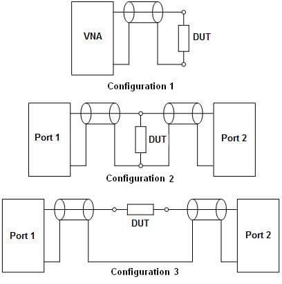
Other configurations
Of course, there are many possible switch configurations corresponding to the wide variety of DUTs. A few connectivity diagrams are shown below. Of course, for help with selecting a switch system for your particular scenario, feel free to contact us at support@coppermountaintech.com and we will be glad to help!

Conclusion
Using an off-the-shelf RF Switch is a practical approach for measuring multi-ports devices especially considering the affordability of such a system compared with switch matrices promoted by test equipment manufacturers themselves. In addition, but customizing the switching system for your test scenario, an off-the-shelf approach provides flexibility of the test setup, in some cases enabling faster tests and increased ease of automation. When selecting a switch for your test scenario, several switch characteristics need to be considered to optimize the performance and accuracy of the test system. During the measurement, attention must be paid to the calibration involved. To ease the measurement process, automation via programming can be used to automate the VNA and RF switch together.
Related Post

Balun Measurements with a 2-port Vector Network Analyzer
July 14, 2022
Balanced measurements are necessary for a number of applications. High-speed digital transmission lines are often employed on printed circuit boards (PCBs) to transport signals with extremely high bandwidths. It is important to be able to verify insertion loss, characteristic impedance, phase imbalance, and crosstalk to adjacent conductors. Antennas are sometimes fed with balanced lines as well and being able to verify the return loss or VSWR of the balanced feed plus antenna combination is useful.

Pulse Modulation Measurements with a Vector Network Analyzer
March 22, 2022
The S5180B 2-port VNA from Copper Mountain Technologies can perform advanced pulsed RF measurement. It can measure the S-Parameters of externally modulated RF signals, or it can measure the internally modulated stimulus signal. In the latter case, the VNA can also produce two logic signals with user-programmable delay referenced to the start of the pulse and with programmable width. Other VNAs from CMT can measure pulsed RF signals but not generate the pulse itself. The S5180B Compact VNA can also measure the modulation envelope of an RF pulse.
Measurement of Electronic Component Impedance Using A Vector Network Analyzer
March 26, 2019
Electrical impedance is an important parameter used to describe individual electrical circuit components or a circuit as a whole. Impedance is a complex number, in which the real part is represented by resistance and the imaginary part is represented by reactance. Once the impedance is determined, one can calculate other parameters such as resistance, inductance, capacitance, scattering coefficient, and figure of merit; draw an equivalent circuit of the measured circuit and predict its behavior over the desired frequency band.
Multiport Testing with CMT VNAs & Off-the-shelf RF Switches
April 19, 2018
Copper Mountain Technologies offers VNA with one port, two ports or four ports. But sometimes, more ports are required, for example for testing multi-port devices. There are many options to achieve multi-port measurements, such as manually connecting and disconnecting each port, or using an OEM switch matrix system. Manual re-connection can be time-consuming to the point of being impractical, depending on the test requirements; on the other hand, test equipment vendors’ switch systems are relatively expensive especially considering these are often repackaged versions of commercially available switches.
Using Compact USB VNAs with an Off-the-shelf Battery
April 19, 2018
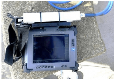
Copper Mountain Technologies provides Vector Network Analyzers without a built-in computer, which enables the VNAs to be highly compact, lightweight and very low power. Those characteristics allow for easily taking CMT’s well-known lab-grade measurement results into the field. There are three main categories of VNA form factor available from Copper Mountain Technologies: small, pocket-size devices (1-Port Cable and Antenna Analyzers); portable 2- port (Compact series devices); and rack mountable (Multiport and Cobalt series instruments). Using the 1-Port and Compact VNAs when A/C mains are not available is very simple, though the latter requires using an external battery pack instead of the ordinary +12V supply. This application note describes both configurations, presents some recommendations, and shows photos taken in the field.