


Measurements in 75 Ohm Coaxial Transmission Lines Using a 50 Ohm VNA
April 19, 2018Introduction
One application of a vector network analyzer (VNA) is the measurement of 75 Ω coaxial transmission lines. In this article, we will discuss making these measurements using the most common type of VNAs, which have 50 Ω test ports, in conjunction with 50Ω‐to‐75Ω Minimum Loss Pads (MLP), i.e. impedance‐matching attenuators with insertion loss of 5.7 dB. Any of CMT’s 50 Ω VNAs can be used to make measurements in a 75 Ω characteristic impedance environment. Most 75 Ω applications are under 3 GHz though so the TR1300/1 and SC5065 are ideal instruments. The use of an MLP affects accuracy of measurements by changing the calibration error and, depending on the location of the attenuator in the measurement circuit, impacts stability of measurements related to test cable bending.
To assess the impact of MLP on the accuracy of the measurements, we will refer to the calibration comparison method [1,2]. We will also compare the additional errors with the typical errors of the VNAs with 75Ω coaxial lines after the most widely used and affordable SOLT calibration (using SHORT, OPEN, LOAD, and THRU standards). To assess the errors dependent on the location of the attenuator in the measurement circuit, it is possible to use the results of practical measurements.
Assessing the additional calibration error caused by the MLP, we will use a number of calibration schemes for a measurement system based on Full-Size VNAs and will apply the calibration comparison method. Let us perform calibrations of the measurement system with the MLPs as shown in Figure 1.
TRLM calibration is one of the most accurate calibrations in the industry today. It is performed using the following standards: THRU, REFLECT, LINE, and MATCH. This calibration technique is recognized as the benchmark calibration all over the world, and a TRLM calibrated measurement system achieves the effective parameters of directivity much better than 50 dB and source match much better than ‐50 dB [3].
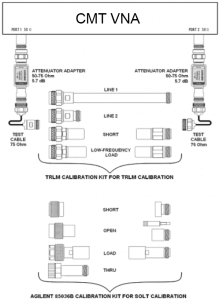
Figure 1
SOLT calibration is the most widely used and affordable calibration technique. In our example we use a high‐quality Agilent 85036B calibration kit, which provides the calibrated measurement system with the following effective parameters: directivity no less than 46 dB at frequencies up to 2 GHz, directivity no less than 40 dB at frequencies up to 3 GHz, source match no more than ‐36 dB, and reflection tracking no more than 0.03 dB.
To assess the measurement system from Figure 1 we will compare two successive TRLM calibrations. Results from Figure 2 confirm that the proposed measurement system allows comparing two calibrations with the following effective parameters: directivity at least 73 dB, source matches at least 65 dB, and reflection tracking being less than 0.003 dB. This measurement proves that the quality of the TRLM calibration performed on Full-Size VNAs practically depends on quality of the LINE and SHORT calibration standards.
Comparing TRLM and SOLT calibrations, we can see that the use of an MLP insignificantly impaired the SOLT calibration parameters compared to the parameters claimed by the calibration kit manufacturer. For example, the measured effective directivity of the given measurement system is better than 46 dB at the frequency of 2.8 GHz, and thus complies with the specifications of the calibration kit manufacturer, i.e. better than 41.2 dB. Therefore, the additional errors introduced into the measurement system due to the use of MLPs are comparable to the range of calibration error when using a commercially available SOLT calibration kit.

Figure 2
Correspondingly, using MLP in a measurement system has a low impact on the measurement errors. That allows recommending the use of TR1300/SC5065 or other 50Ω VNAs of sufficient dynamic range (over 120 dB) and measurement stability with a high‐quality MLP for performing most of VNA RF measurements in 75Ω transmission lines.
It is important to analyze two possible ways of connecting MLP into the measurement circuit (Figure 3).
![]()
Figure 3
The MLPs can be either connected to the VNA ports, or to the end of test cables. The second variant allows using widely available 50Ω test cables that surpasses 75Ω test cables in all the parameters. Even though it looks like the measuring circuit with a high‐quality 50Ω test cable has obvious advantages, such circuit is at a strong disadvantage due to the high sensitivity to test cable bending. Figure 4 shows |S11| parameter of the LOAD standard being measured after calibration and the subsequent test cable bending using the cheapest and simplest 75Ω cable and a several times more expensive and stable 50Ω cable. The bending of the 75Ω cable keeps the |S11| value of the LOAD at about ‐50 dB, while the bending of a much higher quality 50Ω cable results in degradation of the |S11| to ‐30 dB. Such |S11| change actually results in deterioration of the effective directivity of the measurement system to 30 dB, and thus increases the measurement error to an unacceptable value. For example, the measurement of |S11| equal to ‐16 dB will have an error of 2.1 dB compared to the possible error of 0.35 dB; and the measurement of |S21| equal to ‐ 3 dB will have an error of 0.16 dB compared to the possible error of 0.08 dB.
Connection of MLP to the VNA test ports and use of the 75Ω test cables allows for minimizing the impact of the measuring circuit on the measurement accuracy.

Using CMT Full-Size vector network analyzers with 50Ω test ports, 5.7 dB MLP connected to the VNA test ports, and performing SOLT calibration with a high‐quality calibration kit, we can expect the measurement error to be dependent only on the quality of the calibration kit, keeping impact of the 50Ω to 75Ω adapter to a minimum.
References:
1. Dylan Williams, Arkadiusz Lewandowski, Denis LeGolvan, and Ron Ginley “Electronic Vector‐ Network‐Analyzer Verification”, IEEE Microwave Magazine, October 2009.
2. D. F. Williams, R. B. Marks, and A. Davidson, “Comparison of onwafercalibrations,” Automat. RF Tech. Group Conf. Dig., vol. 38, pp.68–81, Dec. 1991.
3. Doug Rytting, “Advances in Microwave Error Correction Techniques”, Hewlett Packard, RF & Microwave Measurement Symposium and exhibition, 1987.