

Pulse Modulation Measurements with a Vector Network Analyzer
March 22, 2022The S5180B 2-port VNA from Copper Mountain Technologies can perform advanced pulsed RF measurement. It can measure the S-Parameters of externally modulated RF signals, or it can measure the internally modulated stimulus signal. In the latter case, the VNA can also produce two logic signals with user-programmable delay referenced to the start of the pulse and with programmable width. Other VNAs from CMT can measure pulsed RF signals but not generate the pulse itself. The S5180B Compact VNA can also measure the modulation envelope of an RF pulse.
There are two modes of pulsed RF measurement, synchronous wideband measurement, also called “Point in Pulse”, and asynchronous narrowband measurement.
Synchronous Wideband Measurement (Point in Pulse):
In synchronous wideband measurement, the S-Parameter measurement both begins and ends within each pulse. See Figure 1.

Figure 1- Synchronous Wideband Measurement
In this case, triggering is necessary to synchronize the measurement period within the RF pulse. If the VNA is modulating the stimulus internally, then this timing is already available to the VNA. If the RF is pulse modulated externally, an external trigger must be supplied for this purpose.
The measurement period of the VNA varies with the IF bandwidth setting. This period is approximately 1.2/IFBW. Therefore, the narrowest measurement period for the S5180B at the highest IFBW setting of 300 kHz is 1.2/300 kHz, or about 4 µS. The narrowest RF pulse to be measured must be wider than this to fully contain it.
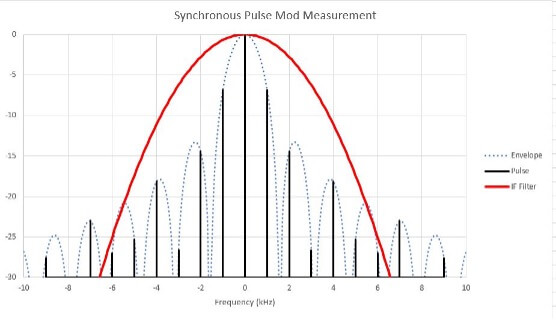
In the frequency domain, the wide IF bandwidth and relatively narrow pulse width are depicted in Figure 2.
Figure 2 – Wideband Synchronous Measurement
This method is called “wideband synchronous” because the IF bandwidth is wide enough to contain most of the pulsed RF energy, the measurement occurs within the RF pulse and the measurement is synchronized to the pulse modulation.
Asynchronous Narrowband Measurement:
In asynchronous narrowband measurement, a string of pulses, ten or more, are asynchronously measured by the VNA. The timing for this might look like Figure 3.

Figure 3 – Asynchronous Narrowband Measurement
It isn’t necessary to synchronize the VNA to the pulse stream. The measurement might begin or end within a pulse or in between but must contain at least ten pulses to prevent excessive ripple. This method results in some loss of dynamic range. Clearly, a measurement of a continuous (CW) signal would give an accurate magnitude measurement. A pulsed RF signal with 50% duty cycle with many pulses occurring during the measurement cycle would contain only half of the total power. The apparent reduction in signal amplitude is 20*Log10(Pulse Duty Cycle).
Since the VNA is aware of the Pulse duty cycle through the programming of the Pulse Period and Pulse Width, the amplitude level change is corrected. Thus, reduction in the duty cycle will not reduce the measured amplitude but the noise floor will increase. This would be particularly apparent if a filter with low insertion loss and high stopband attenuation is measured. The insertion loss would be unaffected, but the noise floor on either side would increase by 20*Log10(Duty Cycle).
The frequency domain representation is shown in Figure 4 below.

Figure 4- Narrowband Asynchronous Measurement
This method is called “Narrowband Asynchronous” because the IF bandwidth is much narrower than the bandwidth of the pulsed RF signal. As can be seen, only a portion of the RF energy is captured in this case and the measured signal amplitude is, therefore, less than the unmodulated signal. This lower signal level results in a loss of measurement dynamic range. The noise floor of the receiver has not changed but the measured RF level is decreased by 20*Log10(Pulse Duty Cycle).
The advantage of this method is the ability to measure much narrower pulses and high pulse repetition rates.
Pulse Profile Measurement:
The profile of an internal or externally generated pulse can be measured and displayed. For example, if the VNA is set to produce a triggered 100 µS pulse. The profile of that pulse may be visualized on the VNA screen in the “Pulse Profile” mode. Figure 5 shows the external pulse setup and the measurement on an oscilloscope.

Figure 5 –
The VNA displays what is shown in Figure 6 below.

Figure 6 – Pulse Profile
The “Profile Time” sets the extents on the X-axis. The left-hand side of the X-axis begins with the rising edge of the external trigger. The 20 µS “Pulse Delay” and the 100 µS “Pulse Width” is clearly seen here at 20 µS per division scale.
This measurement is useful for evaluating the effect of the DUT on the pulse shape, at least within the resolution of the measurement which can be as low as 2 µS at 300 kHz IFBW.
Logic Pulse outputs:
There are two programmable logic outputs that can be programmed to follow the internal pulse triggering. Pulse widths and delays from 100nS to 10S with 100nS resolution are possible. These two outputs, Pulse 1 and Pulse 2, are synchronized to the beginning of the RF pulse and are programmed and enabled from the “Ext Trigger out” and “Ext Trigger In” section of the “Pulse Meas” menu. These pulses might be utilized by the user for triggering additional test equipment. See Figure 7.

Figure 7 – Pulses 1 and 2
Additional Information on Asynchronous Pulse Measurement:
As stated earlier, for asynchronous pulse modulation measurement it’s important to ensure there are at least 10 pulses being processed by the VNA during the measurement period. The results for a 10mS repetition rate pulse with 80% duty cycle measured in a 10 Hz bandwidth are shown below in Figure 8. The measurement period is approximately 1.2/100Hz or 12 mS so there should be about 12 pulses on average within each measurement.

Figure 8 – 10 mS Rep Rate, 10 Hz IFBW 80% Duty Cycle Pulse (about 12 pulses per measurement)
If the IF Bandwidth is increased to 100 Hz such that on average, 1.2 pulses are contained in each measurement, there is a significant amount of ripple as shown in Figure 9.

Figure 9 – 1.2 pulses per Measurement period
And with less than one pulse per measurement period, the result is unusable.

Figure 10 – Less than 1 pulse
Rear Panel Connectors:

Figure 11 – S5180B Rear Panel
These three connectors on the rear panel are used for pulsed RF measurement. All three serve dual purposes. Clearly, when an External Trigger must be input to the VNA, Pulse 2 cannot be accessed.
During Synchronous Wideband (Point in Pulse) measurements with internal triggering, all three of these are outputs. The envelope of the internal pulse modulation is output from the connector labeled “Pulse In”. Optional Pulse 1 and Pulse 2 are output from the first two connectors “Ext Trig Out” and “Ext Trig In” respectively as shown below.

Figure 12 – Pulse Connector Behavior, Synchronous Wide Band (Point in Pulse) Internally triggered mode
When external triggering of the internal pulse generator is enabled, the “Ext Trig Out” Connector can be enabled to be a Ready for Trigger output which informs an external trigger source that the measurement has completed and a new one may be started. The “Ext Trig In” connector accepts the trigger signal from an external source and the “Pulse In” connector is the pulse modulation envelope output as shown below.

Figure 13 – Pulse Connector Behavior, Synchronous Wide Band (Point in Pulse) Externally triggered mode
In Asynchronous pulse mode the “Pulse In” connector is the Modulation Pulse output and the two trigger connectors behave as normal. Pulse 1 and Pulse 2 signals are unavailable. The pulse modulation source may be set to Internal or External. External triggering is not used.
If the pulse modulation is to be generated externally, the “Pulse In” connector is used to pass the modulation envelope to the VNA pulse modulator.

Figure 14 -Pulse Connector Behavior, Asynchronous Narrow Band using internal pulse modulator mode with an external source
Conclusion:
The Pulse Modulation option for the Compact S5180B VNA adds a brand-new level of functionality to the VNA lineup from Copper Mountain Technologies. The ability to generate and measure a Device Under Test with pulsed stimulus allows for convenient measurement and analysis of power amplifier devices without having to resort to elaborate heat sinking which a continuous wave analysis would require. Support for synchronous, asynchronous pulse measurement, and pulse profile analysis greatly simplifies this task.