A Long-Range Solution For Triggering Analyzers with Arduino Microcontrollers
July 15, 2022Introduction
Remote measurements using VNAs are becoming an increasingly popular method due to the increased portability of USB vector network analyzers. For applications such as far-field antenna measurement setup and using a VNA as an insertable remote sensor, the ability to remotely control the VNA becomes imperative. This remote connection is usually accomplished from PC-PC using Component Object Model/Distributed Component Object Model (COM/DCOM) interfacing or Transmission Control Protocol (TCP) interfacing. WIFI is typically used to connect these two separate PCs, but what options exist when WIFI is unavailable? Ethernet can certainly be used to bridge these gaps within a specific range, of course. Fiber optics can also be used for a much greater distance, but then cost becomes a limiting factor.
An affordable and effective option is a simple Arduino & transceiver setup. The cost is modest, while the range is dramatically increased.
VNA Automation Basics
Copper Mountain Technologies (CMT) metrology-grade VNAs are USB-based. USB-driven instrumentation has no built-in computer and separates the measurement module from the processing module. Remote processing allows the VNA to be very portable and lightweight since a PC handles all the processing. Additionally, the CMT VNA software programs will work with any x86 processor, meaning most desktops, laptops, and even some tablets.
When measurements are automated with CMT VNAs, the programming language communicates directly with the software, which then communicates through the USB connection to the VNA. The communication link is important to be aware of since the software must run in the background to make and maintain a connection. If the VNA software is closed during automation, the connection will be lost, and automation will fail.
There are two automation methods for CMT VNAs. One option uses SCPI commands and the other uses COM (Component Object Model) functions. These methods send commands to the VNA software, which triggers the software to perform a function. Method selection depends on user preference. However, before sending any commands, a connection between the VNA software and the automating PC must be made.
Connecting the VNA to the same PC executing the automation programming simplifies the VNA and PC connection. A TCP/IP socket or TCP/IP HiSLIP connection can bridge the two. Either of these connections can be made in one of two ways:
- Standard TCP client library offered by each programming language.
- VISA
These connection methods will not be covered in this application note but are clearly explained in this Automation Guide for CMT VNAs application note.
The key takeaway is that a connection must be established with the VNA software to automate. No matter the method, automation can begin after establishing a connection. A user can make this connection across devices utilizing some of the methods mentioned earlier in the introduction. Microcontrollers themselves cannot connect to the VNA software since they are not x86-based. However, they will be used alongside the automation and will be connected to the automation script itself. Utilizing microcontrollers will be covered later in this application note.
Establishing a Connection Between Two Arduino Microcontrollers
A microcontroller is a microcomputer designed to control embedded systems. Components of a microcontroller are typically memory, peripherals, and a processor. Arduino is a company that produces microcontrollers that pair with their own IDE (Integrated Development Environment), which runs on a computer. The IDE is used to write and upload computer code to the physical board. While Arduino is not the only company to make microcontrollers, their products will be utilized for this application note. Figure 1 is the image of the Arduino Micro utilized. Other manufacturers’ products can also achieve the result of this application note.

Figure 1: Arduino Micro
Peripherals for the microcontrollers can be attached via the header pins available on the boards. The software is entirely open-source. Premade libraries are available to simplify the coding of embedded software. Altogether this makes the Arduino products very user-friendly and easy to learn.
Communication between two Arduino Micros can be done in a multitude of ways. It can be as simple as connecting a couple of jumper wires from board-to-board, or as complex as utilizing radios. Transceivers are very popular peripherals utilized for point-to-point data transmission in these systems. These small radios come in a plethora of frequencies and form factors, making them great for any project.
The 433 MHz RFM69HCW transceiver module from Adafruit was used for this test, as shown in Figure 2.

Figure 2: Adafruit RFM69HCW
The RFM69 connects to the Arduino Micro through the SPI and operates in the lower ISM band at 433 MHz. This frequency provides the signals with a solid range and good wall penetration. It operates off a max 150mA current draw for transmission and roughly 30mA while receiving. The data sheet lists a range of 500 meters line of sight with the proper antennas. Of course, these specifications are indicated with the power output set to max, which is +13 to +20 dBm or up to 200 mW.
The radios utilize AirSpayce’s Radiohead library, with many examples that can be uploaded and tested immediately. These examples range from a 2-node network to a more complex multi-node network. These are a great way to test radios and wiring. Visit this link for more information on connecting to the transceivers.
Connecting the Arduino Micro with the VNA Software
As previously mentioned, the Arduino microcontrollers can’t directly interact with VNA software. The workaround is using Python or any language that can establish a serial connection with Arduino Micro. The serial library with Python was used, as it is open-source and easy to understand.
Once the serial connection is made between the Arduino Micro and Python, communication can occur through the serial port. The serial connection allows Arduino to tell Python what to do, and then Python will send commands to the software. For instance, if the Python script receives a 1 from the Arduino Micro, it will collect data from the VNA software from the current trace, and then send a response to the Arduino. This 1 can be sent from a button press, a sensor reaching a specific value, or many other triggers. The possibilities become endless when considering the opportunities with an Arduino.
Not only can the Arduino talk to Python, but it can also listen to the Python script. For instance, the results are communicated to the Python script if a limit test is performed in the software. The information about whether it is a pass or fail can be sent through the serial port. When the Arduino receives the reply, it can perform a designated action. The designated action could be blinking an LED, playing a noise through a speaker, or outputting a PWM signal to something. Also, there are many possibilities to tie in other testing equipment.
Connecting the Arduino Micro with the VNA Hardware
While the Arduino can’t directly interface with the software, it can interface with the VNA hardware. On the CMT VNAs, there are BNC ports for an input and output trigger. Utilizing the Arduino Micro IO pins, you can directly connect to these. The IO pins can generate 3.3V or 5V square wave pulses; the voltage depends on the model of Arduino. Using this signal, you can trigger the VNA.
For triggering, this makes the scripting connection unnecessary. This is strictly a hardware-to-hardware connection; thus, it is straightforward yet robust. An Arduino to software connection is only needed when you plan to add more functionality to the setup.
Use Cases Once Connected
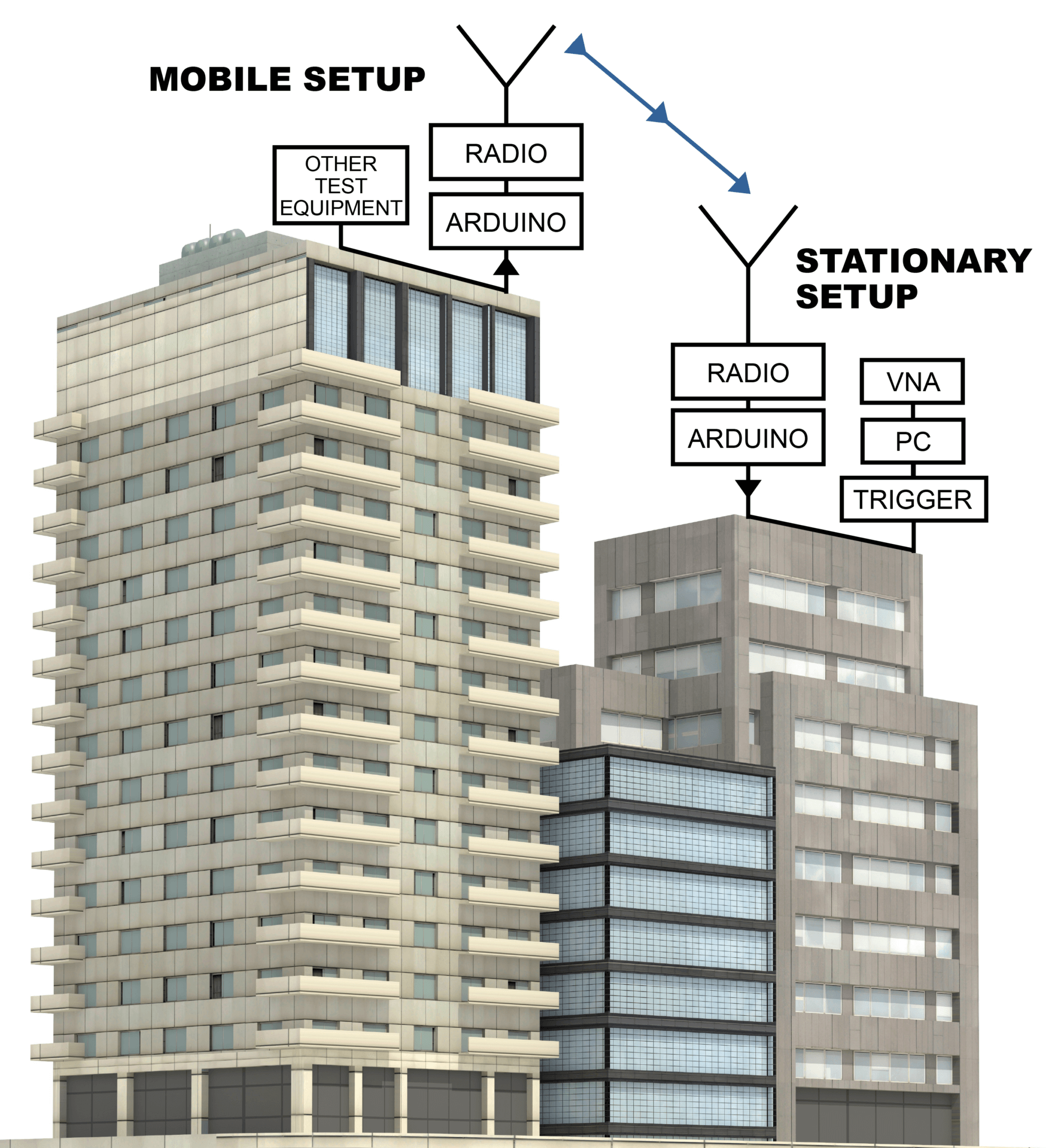
When you combine the previous sections, you can create some very useful setups. To display a real-world use case, this section will describe and explain the example setup. Figure 3 is a simple block diagram of the setup. Note that the Arduino is connected to the PC at the stationary node for this example. This is not necessary if only triggering the VNA.

Figure 3: Dual Node Block Diagram
The scenario involves remotely triggering a VNA from some distance away. Once the sweep finishes, a limit test is run on the trace, and the results are then sent back to the initial Arduino Micro. Only one Arduino Micro is interfacing with the VNA and software, while the other is used only as a mobile transceiver.
Both the stationary and mobile sides of the setups are identical. The only difference is that the stationary node will be connected to a PC, but the mobile node will operate independently. As mentioned in the previous section, technically, you can utilize the stationary node without connecting to any form of PC. The VNA can be triggered using the external trigger port on the rear panel. With no PC, it will limit the ability to communicate with scripts to perform more complicated tasks.
Figures 4 and 5 show the breadboarded and protoboard versions of one of the complete modules. These modules are wired the same as the Adafruit link mentioned above. 3 LEDs (green, red, and blue) were added on open digital pins for signaling things, like a pass or fail of the limit test. A capacitor was added in parallel with the transceiver’s Vin and GND to make sure the Arduino could drive the transceiver at the maximum output power. On the trigger sending node, a simple push button to manually send a trigger signal was included. The node attached to the VNA utilized a BNC to alligator clip. The clip was attached to an open digital pin and ground, and then the BNC to the trigger input on the back of the VNA.

Figure 4: Breadboarded Module

Figure 5: Protoboard Module
After both nodes had been put onto the protoboard, two SMA end-launch adapters were soldered onto the transceivers. To this, a male-to-female adapter attached two quarter wavelength 433 MHz whip-tilt antennas. These 50 Ohm antennas provided a VSWR under 2.0 while being very affordable.
One node was attached to a PC and VNA inside CMT headquarters. The mobile node was powered by a portable power bank and taken outside and down the street. When the button on the mobile node was pressed, it sent a trigger to the stationary node inside CMT headquarters. The yellow LED blinked on both nodes. The stationary node then triggered the VNA and sent the command in the Python script to wait until the VNA finished sweeping. The script then performed a limit test on the current trace. If the trace passed the test, a 1 was sent from the script to the stationary station. If the trace failed, a 0 would be sent instead. After receiving the results, the stationary node indicated the results to the mobile node. Once received, the mobile node flashed the corresponding LED: green for a 1 and red for a 0. The results of the trigger were achieved with only a button press.
This setup was tested in Indianapolis, a large city where the CMT headquarters is located, so testing was limited. However, the configuration achieves a guaranteed 75 meters of range, including the penetration of surrounding buildings’ walls. This range will be far more significant in the intended use case of point-to-point with fewer obstacles in between.
This test operated with a simple Pass/Fail indication, but it would be a simple matter to send actual measurement data over the radio link with speeds commensurate with the link data rate.
For more information on scripting, visit this link for details on Triggering VNAs with Arduino Microcontrollers. In addition, the exact code utilized for this project is available, including the Python file and the two Arduino sketches. For any questions or comments about this portion of the project, please reach out to our expert engineers who are glad to support you.
Conclusion
Interacting and interfacing with test equipment from remote locations is becoming an increasingly necessary topic these days. Engineers can take this concept even further with the benefits of the lightweight USB VNAs from CMT. The portable, compact VNAs allow measurements to be taken directly in the field and on-site. This information can be collected in person or relayed to the software the device runs on.
Integrating Arduinos or any microcontrollers allows for very complex situations to be turned into simple projects. The example shown in this application note is just the tip of the iceberg. The engineers at CMT hope to support engineers around the world to continue to push the boundaries of what is possible in the test and measurement world.
Copper Mountain Technologies aims to innovate and bring new solutions to VNA users every day. If having any trouble using a CMT VNA or to learn more about this project, in particular, contact the CMT support team for assistance.
Related Post
VNA Measurement for High-Speed Digital Signal Integrity
July 7, 2022
High-speed digital signals are commonplace in a variety of applications, and one of the most common carriers of digital signals is the HDMI cable.
mmWave Mixer Measurements with a Low Frequency VNA
April 25, 2022
It is important to use the right equipment for the right measurement to get results that are accurate. Precision millimeter-wave (mmWave) measurements normally require a VNA with built-in capability or mmWave extenders to augment the frequency range. This equipment may be used to evaluate mmWave mixers which are commonly used to up-convert or down-convert 5G signals back and forth from baseband frequencies.
Improve Measurement Accuracy on a Long Setup Cable Using a Portable VNA
February 9, 2022
This article appeared in Microwaves & RF and has been published here with permission. What you’ll learn: Understand the network diagram for VNA measurement error terms. What are the effects of various residual errors on the outcome of the measurement? Learn the only viable solution to the problem of return-loss measurement of a DUT at the end of a lossy feed line. In the real world, vector network analyzer (VNA) measurements in the field often present obstacles to obtaining accurate readings. In this article, we examine the effect of a long coaxial cable between the VNA and the device under test (DUT), and show the benefit of moving the VNA directly to the DUT. Error Terms VNA measurement errors are typically modeled with network flow graphs to depict errors due to internal VNA hardware and the effect of external cables and connectors. In the model, the VNA is assumed to be perfect, and all systemic, non-random errors are modeled by an error box between the perfect VNA and the DUT (Fig. 1). 1. The diagram illustrates a VNA error-term network. In Figure 1, Ed is the Directivity Error, Es is the Source Match Error, Er is the Reflection Tracking Error, and the forward incident signal is normalized to a value of “1.” To understand the Directivity Error, one must realize that there’s some leakage in the VNA directional bridge from the incident signal (signal leaving the VNA) to the reflection port of the bridge. Ideally, no signal would be present on the reflection port if there were no reflected signal, but bridges aren’t ideal, and some leakage always exists. Attenuation of the incident signal and its returning reflection through a lossy cable reduces the desired signal from the reflection port. If the maximum possible reflection at the reflection port of the VNA bridge is reduced and the leakage signal stays the same, then it degrades the effective system directivity. Source Match error is due to the combination of the error in the source impedance of the VNA compounded by departures from a perfect 50-Ω coaxial environment in the connectors and imperfections of the cable. At the end of the feed cable to the DUT, the effective impedance might be close to, but not precisely, 50 Ω. A DUT with an input impedance of precisely 50 Ω would reflect some of the incident signal in this case. This is the Source Match reflection error. The Reflection Tracking error accounts for the loss and phase shift from the VNA to the DUT and back again. It generally falls off with frequency as insertion loss through the cable increases. Residual Error If calibration is performed on a VNA that has short, low-loss cables with precision connectors, one can expect the residual Directivity (D) to be about 46 dB, residual Source Match (M) to be about 40 dB, and Reflection Tracking (T) to be about ±0.1 dB. Residual values are the effective values after performing calibration with a precision calibration kit. Expected error on reflection measurements as a function of these residual errors are as follows: ΔSii = D + T * Sii + M * S2ii + R where ΔSii is the expected error on the reflection coefficient Sii. D, T, and M are defined above and R accounts for any random uncorrected errors. All terms are expressed in linear format and Sii is used to indicate a one-port reflection measurement on any port. Ignoring random error, for high reflection (Sii near 1) from the DUT, the error is dominated by residual reflection tracking and residual source match. For smaller values of Sii, the error is mostly due to residual directivity. Residual directivity is the hard floor beneath which reflection measurements are ambiguous. In practical terms, once the VNA corrects for the leakage signal as much as possible, any reflection signals on par with the remaining error will have 100% error. By simple vector addition, reflected signals that are 10 dB higher the residual directivity will have a ±3.3 dB uncertainty and signals 20 dB higher will have ±1 dB uncertainty. To arrive at these two numbers, simply subtract two vectors with one of them 10 and 20 dB smaller than the other. Figure 2 shows a chart of expected uncertainty on S11 for typical residual values of 46, 40, and 0.1 for directivity, source match, and reflection tracking, respectively. 2. VNA residual measurement error is nominal on S11. The Long-Cable Problem What if one attempts to make a reflection measurement on a long cable? What if there’s 10 dB loss between the VNA and the DUT (Fig. 3)? 3. The DUT is attached at the end of a lossy cable. The additional 10 dB will degrade the residual directivity by 20 dB since the incident signal sees 10 dB of loss and the reflection from the DUT sees it as well. If the chart in Figure 2 is updated with directivity degraded from 46 to 26 dB, we get the uncertainty shown in Figure 4. 4. Degradation of the VNA measurement error is due to excessive cable loss. We see ±3 dB uncertainty for a measurement of 15 dB return loss—not very good at all. There’s no way to remove the loss from the cable so only one simple solution exists: Move the VNA directly to the DUT. To be clear, in the example just described, it would have been necessary to perform calibration at the end of the long cable. That is, we would have had to detach the cable from the DUT and apply the Open, Short, and Load calibration standards. If we must perform operations at the end of the cable near the DUT, why not just calibrate a VNA and attach it directly? In Figure 5, a 6-GHz, 1-port, R60 VNA from Copper Mountain Technologies is shown. It isn’t absolutely necessary to calibrate this VNA since it’s calibrated at the factory. Also, the custom precision connector has been designed to add very low uncertainty to the measurement. Because it runs from USB power, it’s a simple matter to bring this VNA directly to the DUT and perform and save the measurement. 5. Here, the VNA is attached directly to the DUT. For accurate reflection measurements of a DUT at the end of a lossy cable, no other solution is reasonable. Moving the measurement device to the DUT remains the only viable solution and a small, portable device is preferred. Incidentally, one might think it would help to amplify the output power of the VNA. It does not. Increasing the output power will not change the directivity of the bridge; the leakage signal simply increases with the output power of the VNA. The same is true if one adds an output amplifier to Port 1 of a 2-port VNA followed by a directional coupler with the reflection port attached to Port 2. This setup works well to isolate the VNA ports from “Hot” spurious signals on the coaxial line. However, reflection uncertainty for small reflections would still be determined by the coupler’s residual directivity after calibration, which would not differ significantly from the residual directivity of the internal bridge for a 1-port measurement made in the usual configuration. A portable VNA is a powerful addition to the toolkit of any RF professional. This application shows the utility of a small VNA for making otherwise impossible measurements.

Automation Guide for CMT VNAs
September 23, 2021
There are two methods for automating CMT VNAs. One is using SCPI commands and the other is using COM (Component Object Model) functions.
Using USB VNAs with Single Board Computers
July 12, 2019
Copper Mountain Technologies provides VNAs without a built-in computer, which enables them to be highly compact, lightweight, and operate on very low power. These characteristics allow the VNAs to interface with single board computers to work in situations with strict space limitations, and to be integrated in battery-powered systems. This App Note introduces how to set up single board computers to work with CMT USB VNAs.


