

Measurement of High Power Devices
February 14, 2018Introduction
The VNA output ports are capable of sustaining a pre-defined output power level as provided in the datasheet of the manufacturer. Exceeding the power ratings of the VNA ports can lead to incorrect measurement and even cause damage to the VNA. The high input power requirement of the Device under Test (DUT) introduces challenges to the measurement, such as overheating and calibration. Moreover, different measurement techniques, such as load-pull analysis and noise figure measurement require higher input power than the maximum output power of the VNA. Therefore, a booster amplifier is required to boost the input power of the DUT. Then, due to the high reverse isolation of the amplifier, the forward reflection measurement is not possible. To overcome the limitations, Copper Mountain Technologies (CMT) offers the Full-Size 814/1, Cobalt C2209, Cobalt C2409, Cobalt C2220, and Cobalt C2420 models with Direct Receiver Access (DRA) capability to the reference and measurement receivers. The DRA capability enables the accurate forward reflection coefficient measurement when using a booster amplifier. This application note describes the measurement setup for measuring the s-parameters of the high-power devices with DRA to the reference and the measurement receivers.
Requirements for DRA measurement
The traditional 2-port measurement setup introduces several challenges in calibration and measurement when the DUT requires a booster amplifier to provide the required input power. In traditional setup, the DUT is placed between the two ports of the VNA and the reference plane is defined at the two ports of the DUT by calibrating out the effect of all the cables connecting the DUT to the VNA. However, with the addition of a booster amplifier between the VNA port and DUT input port, the calibration plane shifts from the input of the DUT to the input of the booster amplifier. The high reverse isolation of the amplifier impedes the reference plane to be shifted to the input of the DUT as shown in Figure 1.

Figure 1: The measured reference plane vs. the desired reference plane with traditional setup.
The booster amplifier is then included in the s-parameter measurement of the DUT. The effect of booster amplifier can be nullified by adding attenuator with a magnitude equal to the gain of booster amplifier for the transmission s-parameters (S21). However, the forward reflection measurement (S11) is not possible in this setup due to the shifting of reference plane from the input of the DUT to the input of the booster amplifier.
High power DUT measurement setup with DRA
It was mentioned in the previous section that the introduction of a booster amplifier limits the measurement capability in the transmission parameters only. This limitation can be overcome by introducing an external reflectometer between the booster amplifier and the DUT. However, the external reflectometer requires access to both of the reference receiver and the measurement receiver to measure the forward reflection co-efficient. The DRA VNAs available from CMT provides the user access to the reference and the measurement receivers. A schematic diagram of a 2-port VNA with Direct Receiver Access is shown in Figure 2.

Figure 2: Schematic diagram of a 2-port VNA with Direct Receiver Access.
It should be noted in Figure 2 that the input and output ports of the source, reference and measurement receivers must be shorted through a jumper cable for traditional low power 2-port measurement. The high-power DUT measurement setup for measuring forward reflection parameters with booster amplifier is shown in Figure 3. The RF source power is first amplified by a booster amplifier and the amplified signal is passed through two directional couplers to the DUT. The first directional coupler is a forward directional coupler and couples the source signal to the reference receiver. The second directional coupler is a backward directional coupler and the reflected signal from the DUT is coupled back to the measurement receiver. It should be noted here that the directivity and the coupling factor of both the directional couplers should be identical for accurate measurements. The forward reflection parameter is then calculated from the ratio of the two receiver measurements.
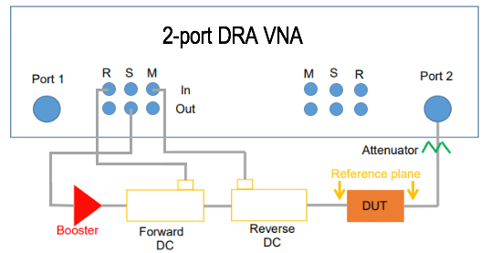
Figure 3: A typical high-power DUT measurement setup with a 2-port DRA VNA.
It can be seen in Figure 3 that with the DRA capability, the reference plane can be chosen at the DUT input and output ports and thus the system cables, amplifiers and directional couplers can be calibrated out from the system measurement. Thus, the measurement setup is capable of measuring the full 2-port s-parameter matrix of a 2-port DUT.
Example of full 2-port s-parameter measurement using DRA
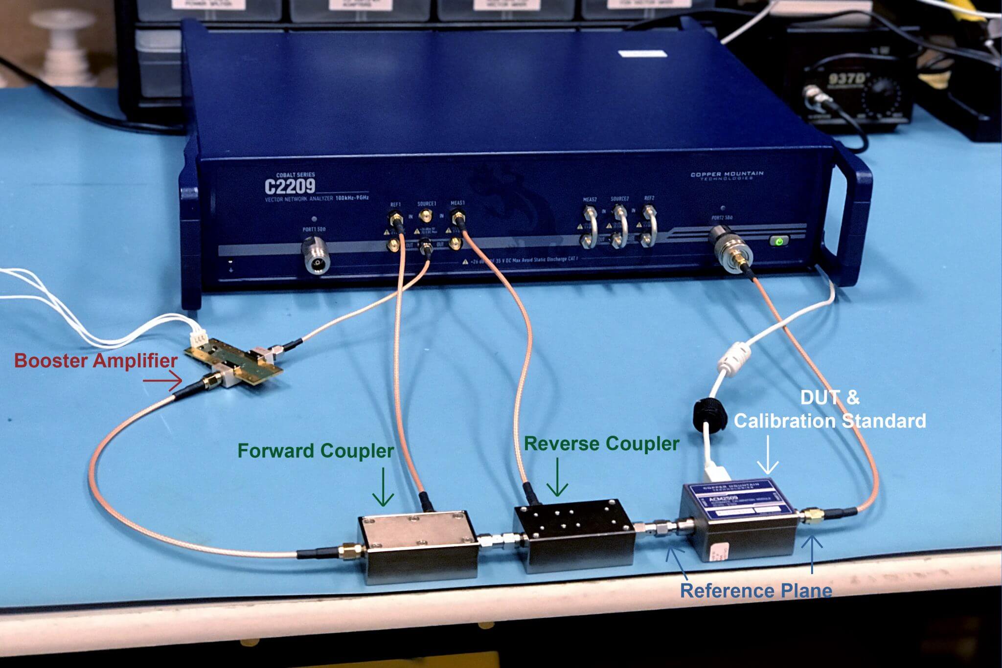
In this section, an example of the full 2-port s-parameter measurement of a band-pass filter using the DRA will be demonstrated using the Cobalt C2209. The measurement setup is the same as discussed in Figure 3. A snapshot of the measurement setup is shown in Figure 4.
Figure 4: A snapshot of the measurement setup.
An ACM2509 (Automatic Control Module) from Copper Mountain Technologies was used to perform a full 2-port calibration at the reference planes as shown in Figure 4. This will calibrate out the effects of all the cables, amplifiers and directional couplers. The calibration can be performed by any standard 2- port SOLT or TRL calibration standards. Then the DUT (a band-pass filter) was inserted and the full 2- port s-parameters were measured. The required input power of the band-pass filter was within the VNA output power capability and a low-power measurement without a booster amplifier was performed to compare the results between them. The measurement results from both the setup are shown in Figure 5.

Figure 5: The measured s-parameters from DRA and traditional measurements.
It can be noted here that the measurement results from both the setups agree with each other. Thus, the CMT VNAs are capable of accurate s-parameter measurement with external reflectometer and direct measurement from the receiver. The Cobalt C2209, or other CMT Direct Receiver Access VNA, can also be used for load-pull measurement as shown in Figure 6.
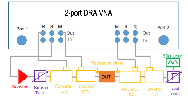
Figure 6: Load-pull measurement setup with a 2-port DRA vector network analyzer.
Conclusion
The high input power required by power devices, such as PA often results in adding a booster amplifier to the measurement setup. The booster amplifier, with its high reverse isolation introduces challenges to calibration and accurate measurement. The effect of booster amplifier in the forward reflection measurement can be calibrated out by introducing an external reflectometer and measuring the reference and the reflected signals directly from the reference and the measurement receivers respectively. This application note describes the measurement setup for measuring power devices with booster amplifier. A demonstration has also been performed with a band-pass filter and the results were compared with those of the low-power measurement with no booster amplifier. This application note will help the user to make the measurement setup for load-pull and noise-figure measurements.