
Custom VNA Applications
June 8, 2023Introduction
In the early days of the cell phone, the head of marketing for Motorola stated the following while holding a Motorola “Star Tac” flip phone in his hand: “This phone is capable of making phone calls in a very convenient way. It greatly enhances our ability to communicate with each other and improves our safety by allowing expedient access to emergency services. But someday, the phone function will be just another feature, perhaps seldom used, and the device will help us organize our lives and provide us with timely and useful information.” He was certainly prescient, and it is a common theme for a technology to evolve from a large, single-function device to a miniaturized version buried within a more sophisticated system.
Figure 1 – CPU Evolution
The modern Vector Network Analyzer (VNA) began in the 1940s as a large rack-mounted device used mostly for radar and RF design central to the war effort. VNAs are now much smaller (Figure 2) and for the first time, available as “bolt-in” modules from Copper Mountain Technologies for use in systems for soil analysis, agricultural product analysis, medical imaging, and industrial sensing just to name a few applications.
Figure 2- Legacy VNA compared to modern Compact VNA
What Kinds of Custom VNAs are Possible?
Almost anything is possible. Copper Mountain Technologies can miniaturize any VNA configuration. Figure 2 shows a 6 GHz 2-Port, “Bolt-In” or embedded VNA. This is a fully functional VNA with the same metrologically sound performance of CMT full-size products and can be provided with a certificate of NIST traceable uncertainties.
It might be desirable to embed a 2-port VNA in a system. Such a system might measure moisture content or gauge the ripeness of melons as in Figure 3. It also might be used to detect tumors in a medical application as in Figure 4.
Figure 3 – Melon Ripeness Measurement
Figure 4 – Umbra Technologies MammoWave® System
Figure 5 shows a 1-Port VNA being used to analyze asphalt integrity. The VNA could be located on the end of the boom and directly attached to the antenna, greatly simplifying RF connectivity.
Figure 5 – Asphalt Analysis
A portable 1-Port VNA, or Reflectometer, can be used to measure soil moisture content. (Arkadiusz Lewandowski et al. studied this in some detail in [1]). 1-port VNAs have been used to measure liquid levels in pipes,wells, or even weightless liquid oxygen in a tank for a space vehicle with NASA.
A 1-Port VNA has been mounted on a drone and used to find survivors buried beneath building rubble after an earthquake.
Figure 6- Drone-mounted VNA
One and Two-Port Modules
Figure 7 shows a 1 GHz, 1-Port VNA. The small size allows it to be easily bolted into a larger system.
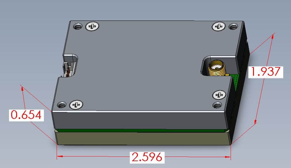
Figure 7- 1 GHz 1-Port VNA
Figure 8, shows the smallest metrologically sound, 2-Port 5.5 GHz VNA in the world. At four inches square and a little over a half inch in height, this VNA could be used in a limitless range of applications including electronic product test, medical or industrial imaging and agricultural analysis just to name a few.
Figure 8- 5.5 GHz 2-Port VNA
These 1- and 2-port modules may be configured and optimized for any specific application. Some configurable options might be frequency range, connector types and position, external time base reference and measurement triggering. Contact Copper Mountain Technologies at 317.222.5400 or support@coppermountaintech.com to discuss your specific needs.
References:
[1] A. Lewandowski , A. Szypłowska, A. Wilczek, M. Kafarski, J. Szerement, and W. Skierucha, “One-Port Vector Network Analyzer Characterization of Soil Dielectric Spectrum”, IEEE Transactions on Geoscience and Remote Sensing, Vol. 57, No. 6, June 2019
Related Post

Introduction to Copper Mountain Technologies' Multiport VNA
February 3, 2023
Introduction Modern RF applications are constantly evolving and demand increasingly sophisticated test instrumentation. 5G systems often have multiple channel outputs for beam-forming, and it is common to have multiple frequency bands aggregated into a single RF front-end sub-system. High-speed digital media often contain multiple balanced lines which might require testing. A 16-port VNA can completely test a cable with four balanced pairs for insertion loss, return loss, near-end crosstalk, and far-end crosstalk. A multiport vector network analyzer is a convenient tool to evaluate all these systems. The SN5090 Multiport VNA The SN5090 is a 9 GHz Multiport VNA, which may be ordered in 6, 8, 10, 12, 14, or 16-port configurations. Figure 1 - SN5090-16, 16 Port VNA Ports on this VNA may be grouped and calibrated separately. For instance, ports 1 through 4 might be grouped and calibrated from 1 to 2 GHz with SMA connectors, while ports 5 and 6 might be designated to make a 2-port measurement from 5 to 6 GHz with N connectors and so forth. Performing a full 16-port calibration requires performing an Open/Short/Load (OSL) 1-port calibration on each port, and potentially a thru calibration between every possible pairing of ports, or 120 pairs. The 1-port calibration is always required, but a mathematical shortcut may be employed to shorten the thru calibration to a total of fifteen thru measurements. This shortcut can be performed by connecting ports 1 to 2, 1 to 3, 1 to 4, through 1 to 16. The new user interface (UI) for the multiport VNA is logically organized, intuitive, and easy to use. Figure 2 - Multiport UI As with all CMT VNAs – except the M series – the SN5090 includes all of the advanced analytical features, such as time domain analysis and gating, at no extra cost. Applications Multi-channel RF systems are quite common in 5G applications. Beamforming requires a number of channels with amplitude and phase control. Figure 3 shows a six-channel system, which might need to be verified with a VNA. Figure 3 - Example of a 6-Channel System for Beamforming Measuring a system such as this with a 2-port VNA would be time-consuming, and if the end result needs to be a full 6-port touchstone file, this would have to be compiled from six separate s2p files. The testing of high-speed digital cables demands the use of a multiport VNA. An HDMI cable contains four balanced twisted-pair transmission lines. To measure the differential insertion loss, return loss, near-end crosstalk, and far-end crosstalk of all four pairs, connect each wire on each end to a different VNA port, for a total of 16 ports as shown in Figure 4. As USB-C evolves to even higher speeds and replaces HDMI, there will be an even greater need to verify the capabilities of the cables and connectors at higher frequencies. Figure 4 - Four Balanced Lines With appropriate fixturing, connectorized cables may be connected and quickly tested with automation, or with pass/fail limit lines set up on the VNA. Front-end RF modules with multiple inputs and upconverted/downconverted outputs are common in satellite communications systems. A multiport VNA can be configured to measure all inputs and outputs, potentially using one or more ports set to zero-span mode to generate fixed LO signals required by the module. Frequency offset mode may be used to measure the conversion efficiency of an upconverter or downconverter. It is often necessary to measure an array of DUTs. The 16-port VNA can make eight 2-port measurements, one after another. This may be needed for production testing or temperature testing of an array of DUTs, as shown in Figure 5, to ensure thermal compliance. Figure 5 - DUT Array Measurement Using a Switch Matrix instead of Multiport VNA A switch matrix may be used to multiplex the ports of a 2-port VNA to any number of ports. A full matrix switching system can connect each port of the VNA to any one of the output ports. This is the most complicated configuration and the slowest. Simpler configurations may only fan out ports 1 and 2 separately to multiple outputs, perhaps to make measurements of the two ends of a bundle of cables. Figure 6 shows a simple 8-way switch that could measure the A and B ends of eight cables. This cannot measure any coupling or interaction between the cables. Figure 6 - Simple 8-Way Fan-Out for 2-Port VNA Taking as an example when eight cables are being tested from 1A to 1B, 2A to 2B, and so on, this simple fan-out configuration would make 8, 2-port measurements in 16 VNA sweeps – one forward and one reverse measurement. That is 2N sweeps for N ports. N or 8 de-embedding files are required. If you need to measure from every port on the left side to every port on the right side, then the number of sweeps rises dramatically. For the case shown in Figure 6, this would require 2*(8x8), which is 128 total sweeps or 2N2 in general. N2 or 64 de-embedding files are required. Measurement time per point for a VNA is typically 1.5/IFBW worst case. For a 1,000 point sweep at a 10 kHz IF bandwidth, this is 150 mS per sweep. The simple (2N) fan-out would require 2.4 seconds to complete, and the more complicated switching (2N2) would require 19.2 seconds. An 8-port full matrix switch is shown in Figure 7. While SP4T switches are more common, you can also use SP8T switches. Here, either port of the 2-port VNA may be routed to any of the eight output ports. This has 8x7 possible switch positions, or N(N-1). A 16-port version of this would be required to perform the same task as the system in Figure 6, measuring eight cables end to end along with coupling and interaction between any pair. This would require 2(16*15) sweeps, or 480 sweeps, taking 72 seconds to complete. N*(N-1) or 240 de-embedding files would be required. Figure 7 - Full Matrix 8-Port Switch Multiport VNA Measurement The multiport VNA switches the stimulus signal from one port to the next while the receivers on every port are active simultaneously, as shown in Figure 8. The incident port is only relevant on the active stimulus port. Figure 8 - Multiport VNA Block Diagram Making the full 16x16 matrix S-parameter measurement only requires 16 switch states and 16 (or N) sweeps. This takes 2.4 seconds for 1,000 points in a 10 kHz IFBW, 30x faster than the full matrix switch approach. No de-embedding files are required, only the 16-port calibration. This is clearly the fastest and most accurate way to make a 16-port measurement, or even a 6, 8, 10, 12, or 14-port measurement. Switch Network vs Multiport Comparison While a switch matrix might be appropriate for a very simple measurement system, the complexity increases dramatically for a full matrix configuration. These complex switches can be painfully slow, as mentioned earlier. Additionally, the need for hundreds of de-embedding files, which may need to be re-generated from time to time, is a daunting prospect. The insertion loss through multiple switches reduces the dynamic range of transmission measurements and greatly affects the accuracy of reflection measurements. A one-way loss through the switch network of 10 dB becomes 20 dB for a reflection measurement. Most VNAs are only specified to 35 dB for reflection, so this would increase to 15 dB. In other words, it would be impossible to measure a DUT with 20 dB return loss with any accuracy. If the loss through one leg is 10 dB, then a transmission measurement would also see two of these losses, and the dynamic range would decrease by 20 dB total. Port-to-port isolation of typical RF switches can run from 45 dB to as high as 90 dB for a high-quality absorptive switch. The internal port-port isolation in the VNA is 140 dB or so, low enough that the leakage signal is below the receiver noise in a 10 Hz bandwidth. This reduction in isolation results in significant degradation of the measurement dynamic range. Mechanical switches have a limited lifetime, usually between 1 and 5 million cycles. In a production environment, this might not last very long. These switches also have a specified repeatability error which cannot be corrected and must be added to the overall uncertainty of the DUT measurement, with one added uncertainty per switch in the path. Conclusion The SN5090 Multiport VNA is a great solution for many applications. The speed, accuracy, and ease of use compared to a switch matrix has been detailed here. Please feel free to examine this product on our website along with our other VNA products and accessories.

Introduction to the Metrology of VNA Measurement
May 31, 2022
A VNA measures reflection coefficients of RF devices and systems. To be very meticulous, each measurement should be accompanied by an uncertainty with a specified statistical confidence interval. To understand the measurement uncertainty, or accuracy, it is important to understand the contributing factors, which are explored in this application note.

Pulse Modulation Measurements with a Vector Network Analyzer
March 22, 2022
The S5180B 2-port VNA from Copper Mountain Technologies can perform advanced pulsed RF measurement. It can measure the S-Parameters of externally modulated RF signals, or it can measure the internally modulated stimulus signal. In the latter case, the VNA can also produce two logic signals with user-programmable delay referenced to the start of the pulse and with programmable width. Other VNAs from CMT can measure pulsed RF signals but not generate the pulse itself. The S5180B Compact VNA can also measure the modulation envelope of an RF pulse.

Automation Guide for CMT VNAs
September 23, 2021
There are two methods for automating CMT VNAs. One is using SCPI commands and the other is using COM (Component Object Model) functions.

Electrostatic Discharge Prevention
July 13, 2021
Electrostatic discharge is a potentially large problem for those working with fragile electronics. If not properly accounted for, it can cause expensive amounts of damage. Luckily, there are steps that can be taken to completely reduce the risks brought on by static electricity. By following the guidelines in this app note, a safe work environment can be created for productive electrical research and development.