What is the Characteristic Impedance of a Coaxial Cable?
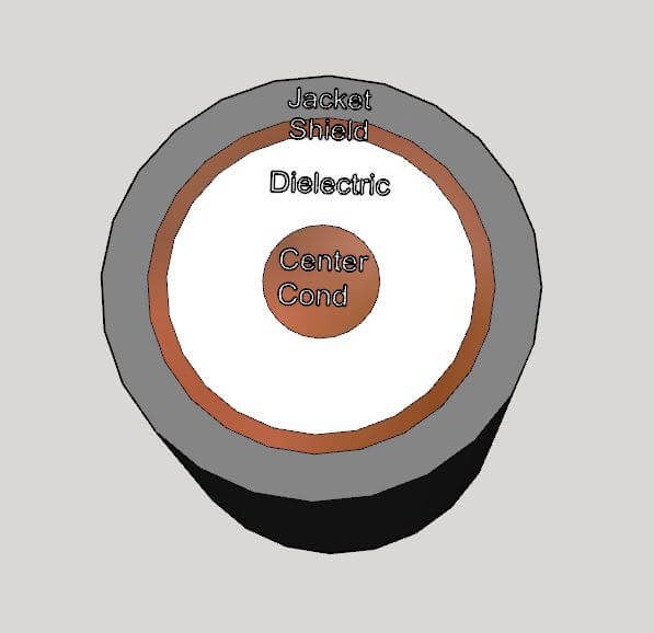
March 22, 2023A coaxial cable is an RF transmission line which consists of a center conductor surrounded by a dielectric medium, a coaxial shield, and often an insulating plastic jacket.

Figure 1 – Coaxial Cable
The inner conductor of the coaxial cable possesses an intrinsic inductance per unit length L’ just like the wire in free space. By virtue of the coaxial shield and the dielectric material, it also has a capacitance per unit length C’. The inductance and capacitance are distributed along the length of the cable, as shown in Figure 4 below.

Figure 2 – Inductance and Capacitance per Unit Length of a Coaxial Cable
If the inductance and capacitance per unit length are known, then the characteristic impedance of the cable is given by:![]()
Low-loss dielectric materials such as PTFE are common. PTFE has a relative dielectric constant of 2.02 to 2.1, but this is commonly processed to create a PTFE foam with a significant amount of air, resulting in lower loss and a lower dielectric constant.
RF travels through the coaxial cable at the guide velocity vg, slower than the speed of light, c:![]()
The relative velocity of propagation is expressed as the percentage of c or:

This number is approximately 65% for solid PTFE cables, and as high as 90% for low loss foamed PTFE. An air-line coaxial cable with only air as a dielectric would have a relative velocity of 100%.
The characteristic impedance of a coaxial transmission line may be calculated from:
Where Douter is the diameter of the outer shield to its inner surface, Dcenter is the diameter of the center conductor, and ∈r is the relative dielectric constant of the medium in between the two.
See this and more important radio frequency charts and formulas in this comprehensive application note.
Related Post

Useful Radio Frequency Engineering Formulas and Charts
February 9, 2023
This application note is a collection of essential formulas and charts for Radio Frequency Engineering.
Using a VNA for Power Plane Impedance Analysis
September 10, 2019
Senior RF Design Engineer Brian Walker at Copper Mountain Technologies was published on Signal Integrity Journal for his article on using a VNA to perform power plane impedance analysis. He writes, "A vector network analyzer (VNA) is an essential measurement tool for RF design and is often used to characterize the performance properties of filters, amplifiers, antennas, and the like. It might be surprising to learn that this versatile tool may also be used to measure and optimize the power supply systems which drive digital, analog, or RF circuits."
Make Accurate Impedance Measurements Using a VNA
June 21, 2019
Three different methods can be applied to accurately measure passive components with a vector network analyzer. A vector network analyzer (VNA) is a very useful test instrument for characterizing RF circuits and amplifiers. But what about measurements of simple passive components? What’s the best way to characterize a chip capacitor or an inductor—or even a resistor? Senior RF Design Engineer Brian Walker at Copper Mountain Technologies wrote an article for Microwaves & RF discussing how to make accurate impedance measurements using a VNA.
Measurement of Electronic Component Impedance Using A Vector Network Analyzer
March 26, 2019
Electrical impedance is an important parameter used to describe individual electrical circuit components or a circuit as a whole. Impedance is a complex number, in which the real part is represented by resistance and the imaginary part is represented by reactance. Once the impedance is determined, one can calculate other parameters such as resistance, inductance, capacitance, scattering coefficient, and figure of merit; draw an equivalent circuit of the measured circuit and predict its behavior over the desired frequency band.


