

TRL Calibration
July 8, 2019Thru-Reflect-Line (TRL) calibration has a number of advantages over the Short-Open-Load-Thru (SOLT) method often used in VNA calibration. For SOLT calibration, the standards must be accurately characterized. The opens and shorts might be characterized by electromagnetic simulation of the physical design or they might have associated one-port “data-base” files obtained by highly precise measurement.
If data-base files are not available, the Open and Short will be specified by a short delay followed by a parasitic capacitor or inductor to ground. The parasitic capacitance of the Open or parasitic inductance of the Short is specified by a third order polynomial over frequency. The “Thru” is usually assumed to be lossless with perfect characteristic impedance and Its delay is usually specified. If the delay of the thru isn’t known, it can be calculated by the VNA. Unless a data-base file is provided for the load, it is assumed to be perfect. Creating a “perfect” broad-band load is exceedingly difficult and in SOLT calibration, the accuracy of the load is a large contributor to the final uncertainty of the measurement.
Clearly, using a data-based SOLT calibration kit is highly desirable, but to be useful, each kit must be precisely measured with unique characterization files provided for each kit which adds significant cost. Calibration kits characterized with polynomials are more affordable since every kit with the same mechanical design will share the same polynomial set.
By contrast, TRL calibration is made up of a Thru Line, a Reflect standard and another Line. In true TRL, the Thru standard is zero length and the Line is 90 degrees long at the center frequency where the calibration is to be performed. The Reflect can be anything with a reflection magnitude of 1; that is, Short, open, or anything else along the circumference of the Smith Chart and does not need to be characterized. No load is needed. The delay of the Line does not need to be known with precision. Clearly, it is much easier to create calibration standards like these for very high frequencies. One important requirement though is that the characteristic impedance of the Line must be very precise and must not vary with frequency. Precision air lines are often employed for this purpose.
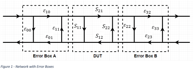
In order to understand the calibration process, it’s important to understand the error model. Figure 1 shows an S-Parameter Flow Diagram for a Device Under Test (DUT) with Error boxes on each side that correspond to the systematic errors which must be removed by the calibration process. Solving this problem clearly requires the determination of eight unknowns. Full 2-port measurement of the thru provides four of these. Measurement of the line provides another four and each reflect provides one more each for a total of ten. The phase of the reflection and the propagation constant of the line is determined by this extra information.
This is a very useful result. As mentioned above, characterization of a reflect, either Open or Short is usually given by a delay and a third order polynomial of fringing capacitance of the open and spurious inductance of the short. A definition which is constant for every calibration kit of a certain manufacture. Clearly there will be some variation from piece to piece. TRL makes this characterization superfluous and thereby results in greater accuracy.
![]()
The frequency range of a TRL Calibration kit depends on the “line” length. The “line” can be used over a frequency range where it is 20 degrees to 160 degrees longer than the thru or 90 degrees +/-70. For true TRL, the thru is zero length but it can have a finite and hopefully short length. Technically, calibration with a non-zero thru length is called LRL (Line Reflect Line). The VNA calibration software is informed of the delay length of the thru in the definition file such that the reference plane ends up properly at the connectors and not half-way along the thru. For a larger frequency range, multiple lines may be used with slightly overlapping frequency range.
For instance, one might have a “thru” of 132 pS delay and a “line” of 345 pS delay. The line is 213 pS longer than the thru. The center frequency where the line is 90 degrees longer than the thru is:
90/(360*213pS) = 1174 MHz
The lowest frequency where this line could be used is where it is 20 degrees longer than the thru or:
20/(360*213pS) = 261 MHz
and the highest frequency of use is at 160 degrees longer than the thru or:
160/(360*213pS) = 2086 MHz
When the line is entered in the calibration kit definition, its actual delay and the lowest and highest frequencies of use should be entered.
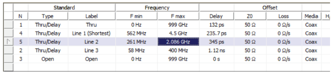
“Line 2” in the above kit definition is entered in this way.
For a definition with multiple Lines and overlapping ranges, the range of the last measured Line is used by the VNA. As mentioned previously, the delay of each Line does not have to be known to great accuracy. It is only important that its use is limited to frequencies where it is between 20 and 160 degrees. The calibration method becomes undefined and inaccurate for Lines near 0 degrees and 180 degrees so this must be avoided.