

Testing & Matching PCB Antennas
April 19, 2018Introduction
Connecting to an Antenna Under Test (AUT) integral to a Device (DUT) may involve some trade offs between measurement accuracy, electrical considerations, and mechanical ruggedness. In this paper, we describe some aspects of connecting a PCB antenna to test with practical advice for such test and measurement scenarios.
Cable Length and Type
Regarding the choice off cable, here are some points to consider:
- Test Cable: The test cable should be long enough to place the test instrument out of the near field of the AUT and preferably a few wavelengths away. This reduces reflections off the test instrument itself so the antenna measurement will better approach the limits of the test environment.
- Test Cable Type: The thinner and more flexible the cable, the less strain relief required for ruggedness under test; on the other hand, the thinner the cable, the greater the attenuation loss which limits the measurement accuracy. To follow is a table of cable types typically available in commercial cable assemblies.

If the required test cable length introduces significant loss, it may be possible to include the coaxial adaptors and test cable in the instrument calibration using a tightly constructed short, open, and a 50 ohm chip resistor on a brass board of similar construction to the DUT.
Use of a Simple Switch at a Test Port

A test port and test cable of the appropriate type reduce the need for strain relief as the cable can be connected just before measuring. A right-angle connector at the device end may further reduce stress and allow easier routing through the device housing. Commercially prepared cable assemblies are available from Amphenol, Crystek, Emerson Network Power Connectivity/Johnson, Hirose Electric Co Ltd, KSM Electronics, Molex, Phoenix, Pomona, RF Solutions, Samtec, Taoglas Limited, and TE Connectivity. An excellent source for these is www.digikey.com. Note that most ultraminiature connectors have a mating life on the order of a few dozen cycles, but failure will become self-evident in the measurements.
Testing Without a Test Port
If there is no test port, a 50 ohm match is typical at the output matching network of a mixed signal SOC, duplexer, diplexer or the like, or along a feedline trace to the antenna. The ideal test point has close by access to the antenna’s ground plane, preferably one well reinforced with vias.
In both the “horizontal” or “vertical” launch, the goal is to maintain the TEM modes that exist between the center conductor and shield of the test cable the feedline microstrip and its ground plane through the transition between them. An excellent discussion of transition issues and some of the alternatives can be found at Artech House here.
A 50 ohm microstrip feed line may be as little as 0.03 to 0.1mm (.015” to .025”) wide if over an embedded ground plane of a thin circuit board assembly. Protecting such a thin trace from being pulled up by the test cable requires a mechanically sound connection between the cable sheath or shield and the ground plane, preferably in an area where the ground plane is reinforced by vias.
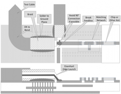
Horizontal Launch
For a horizontal launch, to the extent possible the test cable should access the broken microstrip feedline trace directly from the ground plane and in the direction of the feedline. Keep the feed line and center conductor and their separate ground return currents close by, in proximity, parallel to each other, and minimally different in length. Avoid 90° connections and bends until both currents are safely within the test cable. Eisenhart’s “edge-launch design” (described at the Holzman link above) can be approximated even if the test point is not on the edge of the circuit board.
Using a Balun
A further refinement might help exclude the test cable from the measurement if the DUT has insufficient ground plane and common mode currents on the cable result. This can be done by forming a 1-turn loop around the minimum bending radius for a semi-flexible or hand-formable test cable, or with a ferrite bead or two placed over the test cable where it departs from the ground plane. While ferrite beads are not characterized above 500 MHz and all of them lose performance as frequency increases, they are inexpensive and unlikely to impair the test results. Type 61 ferrites are usually recommended above 300 MHz but Type 43 is available in a greater range of dimensions and may work.
A bead can be selected for fit and evaluated by placing a sample at the shorted end of a coaxstub and extending the R54 port to that point. As a useful example, the Kemet B-20L-44 (Digikey 399-10822-ND in an RG-178 stub demonstrated |Z| in excess of 58 ohms out to 3 GHZ, which includes the GSM, UMTS, and LTE to Band 7. It was in excess of 30 ohms out to 5GHz. Any common mode current from the DUT can be arbitrarily reduced by stacking multiple beads.
Conclusion
The typical PCB antenna in the 2.4GHz ISM bands and up is a compromise to begin with because of multiple band requirements and size and space constraints; accordingly, the typical SWR may be far more significant than reflection or attenuation from a less than ideal test cable interface. Every device will be different but keeping the TEM modes in mind in making the test connection won’t hurt and will make for the most accurate test. If you have questions about the potential test approaches for your application, please contact us at support@coppermountaintech.com and we will be glad to help.