

Power Integrity Measurements with CMT VNAs and Picotest Accessories
April 19, 2018Introduction
Power integrity measurements are essential in all modern electronics, including RF and Microwave circuits. Poor power integrity results in spurs and degraded phase noise. As is the case with RF and high-speed signals the goal is a flat, frequency independent impedance. Unlike RF and high-speed signals, the magnitude of the impedance is not defined, and must be determined based on the circuit noise tolerance. The power distribution network (PDN) measurement includes the voltage regulator, printed circuit board planes and decoupling capacitors.
Measuring capacitors, ferrite beads and the PDN impedance can be a challenge, including very low impedance magnitudes large dynamic range and a wide frequency range. For example, the impedance of a 10 nF capacitor at 20 kHz is approximately 800 Ω while at its series resonant frequency it is on the order of 10 mΩ. Similarly, a ferrite bead might be 10 mΩ at 20 kHz and more than 500 Ω at resonance occurring as high as 100 MHz or more.
2-Port Shunt
The Copper Mountain Technologies’ compact VNA series offers the dynamic range and sensitivity required for these measurement challenges.
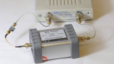
The measurement sample or DUT is placed in shunt with the 2 ports as shown in Figure 1. If the DUT includes a DC voltage, DC blocks, such as the Picotest P2130A should be included to isolate the DC voltage from the sensitive VNA inputs. The DC resistance of the two interconnect cable shields appear in parallel with each other and in series with the DUT. At higher frequencies the cable coupling offers sufficient isolation. A coaxial common mode transformer is required for measuring low impedance magnitudes at low frequency. The Picotest J2102B common mode coaxial transformer maintains a good 50Ω match up to approximately 300 MHz.
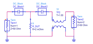
Figure 1: The 2-port shunt measurement setup including the DC blocks and coaxial common mode transformer (see text).
Components are generally mounted to a small circuit board, which includes RF connectors to simplify the connection to the VNA ports. A 1 mΩ resistor is shown connected to the VNA in Figure 2. Prior to connecting the DUT, a full 2 port calibration is performed, at the cable ends. This calibration includes the interconnecting cables as well as the P2130A DC blocks and the J2102B coaxial transformer if they are included in the measurement.

The 2 port measurement is converted to impedance using the 2-port shunt transformation located in the Analysis menu.
Measurement of a 1 mΩ resistor and a 5 mΩ resistor using the setup of Figure 2 are shown in Figure 3.
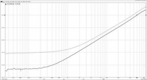
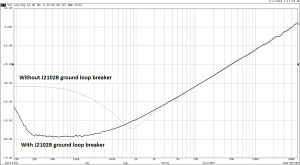
Figure 3: Measurements of 1mΩ and 5mΩ resistors.
The measurement markers indicate -58.5 dBΩ (1.18 mΩ) at low frequency and -15.5 dBΩ (0.168Ω) at 59.6 MHz. corresponding with an inductance of 449 pH.
The impedance of a 2.2 uF X5R ceramic capacitor is shown in Figure 4. The capacitor measures -10 dBΩ at 300 kHz (0.316Ω) -48 dBΩ at the 6 MHz series resonance (4 mΩ) and -20 dBΩ (0.1Ω) at 50MHz.
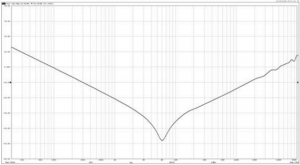
Figure 4: Measurement of a 2.2uF X5R ceramic capacitor.
CMT’s Compact VNAs can easily perform power integrity measurements using just a few additional accessories. Individual components should be mounted to a PCB for high quality, repeatable results. All of the accessories required as well as characterized device mounting boards and PDN probes are available from Picotest.
Conclusion
In conclusion, here are a few tips to ensure optimum results:
- Keep the cables connecting the VNA to the DUT as short as practical.
- Since the cable shield resistances are in parallel make one connection very short. If possible connect the DUT using just a coaxial adapter rather than a cable.
- A common mode coaxial transformer, such as the Picotest J2102B, or the Picotest J2113A active differential amplifier, MUST be included in order to get the correct answers. It should be placed on port 2.
- Always measure a known value each time you recreate the setup. We often measure a sample resistor as in this application note. Picotest offers a useful Parts Kit of known values that is perfect for checking all types of power supply test setups. They also offer a blank board kit if you would like to populate your own part.
- Use a log frequency sweep.
- Very low IF BW is required for low impedance measurements.