

RF Mixer Characterization
April 19, 2018Introduction
Mixers are 3-port devices that incorporate nonlinear elements, typically diodes or transistors, to produce the sum or difference of two input frequencies. For example, in transceivers mixers are used to translate radio frequencies (RF) to intermediate frequencies (IF) to allow easier, cheaper, and more accurate processing as well as to translate intermediate frequencies to RF for communication, especially over antennas which are more efficient and smaller at higher frequencies.
Engineers developing mixers or integrating mixers in systems often need to measure mixer performance, including conversion loss, phase and group delay, the 1 dB compression point, isolation between ports, and port VSWR. Measurements characterizing these parameters are easily performed on Vector Network Analyzers (VNAs) with advanced calibration techniques, including Scalar Mixer Calibration (SMC) and Vector Mixer Calibration (VMC). Both of these calibration methods are described in detail in the operating manuals of Copper Mountain Technologies’ S2 family of VNAs, available for download at www.coppermountaintech.com.
This application note will give a brief overview of mixer fundamentals, describe important mixer characteristics, and detail various measurement processes.
Introduction to Mixers
The primary function of mixers is to sum an intermediate frequency (IF) with a local oscillator (LO) frequency to produce a RF signal or to subtract the LO frequency from the RF to produce an IF signal. However, in both applications the additive and subtractive frequencies result, yielding upper and lower sidebands. Engineers typically use filters to select the frequency of interest. In this paper, we will describe the input as RF and the output as IF for convenience. The VNA’s IFBW will act as our bandpass filter, selecting the sideband of interest.

Nonlinear devices exhibit frequency combining since their output is not directly proportional to their input. For example, diodes convert input voltage to current draw through the p-n junction, meaning the current frequency will correspond to the modulation of the input voltage, not directly to the frequencies present in the voltage signal. Due to nonlinearities in mixers, intermodulation distortion—which is akin to harmonic distortion for multiple frequencies—will result in spurious, higher-order frequencies in the system, yielding terms such as 2*RF+0, 2*RF+LO, 3*RF+2*LO, and etc. that contribute to conversion loss. Conversion loss is an important characteristic of mixers that relates output IF power to input RF power.
This application note contains measurement results obtained with an experimental demonstration system. For this demonstration, Copper Mountain Technologies’ 804/1 VNA was used to perform mixer measurements. Minicircuits Coaxial Frequency Mixer ZX05-1L-S+ was the Mixer Under Test (MUT); a second mixer of the same part number was also used as the reference mixer for vector mixer calibration (VMC). Additionally, Copper Mountain Technologies’ demonstration BandPass Filter F01 was used in VMC. IF Bandwidth was kept at 100 Hz throughout to minimize spurious signal interference, unless otherwise stated.
Scalar Mixer Calibration
To perform measurements on a single mixer, engineers first need to perform scalar mixer calibration (SMC) of their VNA, which will account for the frequency offset introduced by the mixer. The VNA will supply an input IF or RF frequency signal to be upconverted or downconverted to the frequency of interest at the mixer output. Because the output frequency at VNA Port 2 does not match the input frequency from Port 1, at Port 2 needs to be configured for frequency offset mode. In SMC, standard Short-Open-Load-Thru (SOLT) calibration is performed, with the caveat that calibration must account for all frequencies of interest. This can be done in either of two ways:
- By enabling frequency-offset mode, each SOLT measurement may be taken over both supplied frequency ranges, which requires more time but yields a more accurate calibration.
- Frequency-offset mode is not enabled and a single SOLT measurement cycle is performed over the full frequency range of interest, which speeds calibration but results in interpolation during actual measurements. The process of SMC is described in detail in the operating manual for all of Copper Mountain Technologies’ S2 VNA family.
Conversion Loss
Conversion loss is a measurement of the difference between the IF power transmitted and the RF power supplied, calculated as Lconv = PRF − PIF, where PRF and PIF are in dBm and Lconv is in dB. Unless an amplifier is housed in the mixer, output power from a mixer will always be lower than the input RF power. Conversion loss can be considered a primary metric of mixer performance because it correlates directly with other common metrics like isolation, VSWR, and 1 dB compression; specifically, a high-quality conversion loss requires solid specs on isolation, VSWR, and the compression point while the converse is not necessarily true.
It is possible to perform conversion loss measurements with a fixed IF signal or with a swept IF signal. If the IF is fixed, then the RF will be swept synchronously with the LO. If the IF is swept, then the RF will be swept synchronously but the LO is held constant. Each of the following measurements was performed with SMC.

These conversion loss measurements were performed with the IF frequency fixed at 30 MHz and the RF Power at -25 dBm. The four measurements correspond to whether the LO or RF was the higher frequency and whether S12 or S21 was measured.
Overall, the similarities among these results suggest the mixer is fairly reciprocal. Of significant note, the S21 measurements are downconversion from the RF frequency and the LO, whereas the S12 measurements are upconversion from the 30 MHz IF and LO frequencies. Copper Mountain Technologies’ S2 family of VNAs support frequency offset mode between ports, as was used here, or between the measurement and reference receivers of a single port.
The following conversion loss plots were taken of the mixer hooked up to the VNA in two separate configurations. In one, the RF signal was downconverted to IF and the IF signal was upconverted to RF. In the other set, the reverse occurred. This compares reciprocity in both upconversion and downconversion as well as in both ports of the VNA. Generally, the IF-RF ports are considered to be reciprocal and upconversion/downconversion is considered to be reciprocal. As you can see here, while the values are all very similar, they are not perfectly reciprocal.


SMC Conversion Compression
As RF input power increases beyond a small signal, it begins to drive the mixer out of the linear region of operation into compression, where increases of power input do not yield equivalent increases in power output. In general, engineers measure the 1 dB compression point to determine the high end of the linear region of operation.

Here we performed a sweep of IF Power, with LO Power = 5 dBm and LO frequency = 3 MHz. The IF frequency is set to 100 MHz and the upper sideband RF signal is 103 MHz. The 1 dB point is approximately +0.75 dBm.
Isolation Measurements
Isolation measures the amount of power that leaks between ports, which occurs due to internal impedance mismatch and limitations of coupler performance. Mathematically, PLO to RF isolation = PLO in − PRF out, where PLO in and PRF out are specified in dBm and PLO to RF isolation is specified in dB. Isolation generally refers to six terms: LO-RF and RF-LO isolation; LO-IF isolation and IF-LO isolation; as well as RF-IF isolation and IF-RF isolation. However, these terms are highly reciprocal, so it is standard practice to only measure LO-RF, LO-IF, and RF-IF.
Since the LO signal power is normally much greater than the RF or IF signal power, LO-RF and LOIF are the most important isolation measurements for systems engineers. Design engineers may pay closer attention to RF-IF isolation since it plays a larger role in the conversion loss of the mixer. LORF leakage is a serious concern for engineers using mixers with antenna receivers attached directly to the RF port since regulatory agencies place strict limitations on the RF power that can be radiated by receivers.
The setup for various isolation measurements as well as the measurement results are displayed below. For LO-IF isolation, the RF port is terminated with a load and an LO signal is generated. For LO-RF isolation, the setup is similar, but the IF port terminated by a load instead. For RF-IF isolation, the LO signal is generated while feedthrough to the IF port is measured. Each of the following measurements was performed with standard Short-Open-Load-Thru (SOLT) 2-port calibration. The LO signal was set to 501 MHz so as not to interfere with the measurement data.

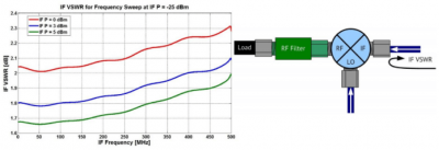
VSWR Measurements
VSWR Measurements characterize how well the input impedance of each port on the mixer matches the impedance of the connecting device, which is generally 50 Ω. This is important since reflections off of the ports can cause remixing within the mixer, leading to ripples in the measurement data. Since mixers have three ports, VSWR measurements depend on the conditions of the other two ports, so they must be terminated as they will be during operation. For instance, if the IF or RF ports are connected to a filter, that filter will need to be present during the reflection measurement. For our measurements, we did not include a filter since their purpose is to serve as an example.
Note: The power levels specified here are the output at the ports of the VNA—the power that enters the MUT will be lower by 0.1 – 0.2 dB due to attenuation in the cable. Each of the following measurements was performed with standard SOLT 2-port calibration.
As you can see below, the port matches on this mixer are good, but not great, leading to minor ripple in the reflection measurements.


Vector Mixer Calibration
Compared with Vector Mixer Calibration, scalar mixer calibration enjoys advantages of both simpler setup requirements and more accurate scalar measurements. However, vector mixer calibration (VMC) is necessary for measurement of mixer phase and group delay.
VMC requires a second calibration mixer and filter in addition to the mixer under test (MUT). The filter needs to have low loss in the passband, so that there is little measurement uncertainty, but it should be strongly reflective to other frequencies so that spurious signals do not interfere with the measurement result. The calibration mixer has several requirements as well:
- The frequency range must be equal to or greater than the frequency range of the MUT
- Return loss should be high to prevent spurious production from reflections
- The conversion loss should be less than 10 dB
- Conversion loss should be reciprocal in magnitude and phase: signal from RF to IF ports should be equivalent to the signal from IF to RF ports
- Spurious response needs to be low
- Isolation between LO and RF as well as LO and IF must be at least 20 dB
- The RF power level must be operated in the linear region to ensure linear reflections, typically 30 dB below the LO power level
- The LO power level at calibration must be equal to the LO power level at operation since the LO level affects many parameters of mixer operation, especially the conversion loss. The LO power level should also be equal to the LO power of the MUT, which can be achieved with a power splitter
Based on our analysis of Minicircuits Mixer ZX05-1L-S+, the mixer meets all the specifications for a calibration mixer. Additionally, the Copper Mountain Filter F01 meets the requirements for a calibration mixer. You too can use a mixer identical to your MUT if it fulfills the requirements for calibration, as we have elected to do here.
During VMC, the calibration mixer and filter never need to be disconnected or moved during the calibration or measurement process—they should remain in the setup.

VMC is based on up- or down-converting a frequency to an intermediate level, sending the intermediate signal through a filter to remove spurious products, and then down- or up-converting the frequency back to its original level, so that frequency offset is not required and phase information can be measured by the VNA. In order to accurately measure the MUT, the calibration mixer and filter are de-embedded from the measurement.

Conversion Loss
Here, conversion loss was performed with VMC. Of significant note, VMC assumes the calibration mixer is perfectly reciprocal. We know this is not the case (see SMC), but since the MUT and calibration mixer are the same model, the VNA will “measure” nearly identical S21 and S12 measurements to keep in line with its calibration assumptions.

The RF and IF frequencies are swept while the LO was kept at 400 MHz. The upconverted signal was sent through a 420 MHz – 600 MHz (3 dB points) filter. This was coincidentally the range we chose for our measurements.
Conversion Loss

LO power was supplied at 1.1 dBm. Using the marker search function on Copper Mountain Technologies’
804/1 VNA, the 1 dB compression point was located precisely. The IFBW was set to 5 Hz to reduce ripples and the measurement was performed at 100 MHz. The 1 dB point is found to be about -2.17 dBm.
Conclusion
Measurements of mixer performance include conversion loss, phase and group delay, the 1 dB compression point, isolation between ports, and port VSWR. Measurements characterizing these parameters are easily performed on Vector Network Analyzers (VNAs) with advanced calibration techniques, including Scalar Mixer Calibration (SMC) and Vector Mixer Calibration (VMC). Compared with Vector Mixer Calibration, scalar mixer calibration enjoys advantages of both simpler setup requirements and more accurate scalar measurements. However, vector mixer calibration (VMC) is necessary for measurement of mixer phase and group delay.
Copper Mountain Technologies’ 2-port 2-path VNAs include frequency offset mode, SMC, VMC and all other functions for accurately characterizing frequency-translating components and devices such as mixers. Please, if we can help you with your mixer measurement needs, feel free to contact us at support@coppermountaintech.com.