2-Port Impedance Measurement - Joint Application Note with Picotest
September 2, 2021
By Benjamin Dannan and Steven Sandler, Picotest.com, and Subbaiah M. Pemmaiah, Coppermountaintech.com
High speed Printed Circuit Board (PCB) design requires well designed Power Delivery Networks (PDN) to support today’s FPGAs and custom mixed-signal ASICs. The PDN contains important impedance information that can tell a designer how a system will react to dynamic currents and the impact of PCB layout. If we consider the PDN as a transmission line between the Voltage Regulator Module (VRM) and the load (ASICs), then a starting point for a good PDN design is the VRM.
Today VRMs need to supply power to multiple VDD cores to support FPGAs and/or custom ASICs using multi-gigabit Ethernet, PCIe, and DDR memory interfaces. With that being said, vendor information for a VRM’s output impedance is not available and not always accurate when it is supplied. Further, measuring ultra-low impedance on multiple VRMs or multi-topology DC-DC regulators is a challenge for any design engineer.
The 2-port shunt-through impedance measurement is the gold standard for measuring a VRM’s output impedance in the microOhm and milliOhm region [1]. However, it is not always possible to make these measurements with direct coaxial connectors designed into the PCB or Device Under Test (DUT). Therefore, when a designer makes these types of measurements with a Vector Network Analyzer (VNA), the method of connecting the DUT requires attention to detail to ensure inductance and various error sources are minimized to allow an accurate measurement. To get the most out of your VNA, you need to use the right probes and accessories to obtain an accurate and repeatable measurement. With a browser probe, like the P2102A, you can quickly characterize multiple VRMs to verify stability or to check the simulation model accuracy during the initial PDN design.
The Picotest P2102A 2-port PDN transmission line probe is a browser probe that achieves a very low inductance at the tip to mitigate space constraints on a dense PCB, while eliminating the need to solder COAX, add additional coaxial connectors, or other test points necessary for impedance measurements. It is especially useful when there are dozens of rails to assess and there isn’t time, or PCB iterations available to provide test point implementations for each. Repeated measurements are simplified because connection to the power rail is by simply touching the tip to an existing output capacitor pad. This browser probe comes with four (4) probe tips to allow measurement across a variety of SMD packages on a PCB including 1206, 0805, 0603, and 0402. The P2102A probe tips are available with 1X, 2X, 5X, and 10X attenuations as well as AC coupled. This allows flexibility for users to measure across a wide range of voltages. For instance, the 2X probe can measure 6Vrms without DC blocks. The tradeoff is the probe attenuation increases the impedance floor. In short, this 2-port P2102A probe is best suited for VRM, power plane, and decoupling measurements. An added benefit is that you can use Picotest’s Non-Invasive Stability Measurement (NISM) software with Copper Mountain Technologies’ VNAs and software to assess the power supply’s stability at the same time as you assess the PDN [2].
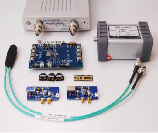
The goal of this document is to show design and test engineers the process of how to set up and use Copper Mountain Technologies (CMT) VNAs with the Picotest P2102A browser probe to accurately measure the impedance of any VRM or power rail efficiently and quickly. The set-up shown below uses the Compact S5085 VNA, which was discontinued and replaced by the Compact SC5090 VNA. The same steps would be valid for all full 2-port and 4-port CMT VNAs. This document will also show you how to use this browser probe as a quick GO/NO-GO tester. In this application note, two DUTs will be measured as detailed by the process shown in Figure 1.
Note: The Picotest LM20143 test boards come as a set, including a Flat impedance and Not Flat (NF) impedance designs. Throughout this document we’ll refer to this as its impedance profile.
2.0 Measurement Setup
The P2102A-2X probe tips include 50 Ω series resistors (Rs), which can be set up/accounted for in the Matching Circuit Modeling Plugin (MCM). Figures 3 and 4 provide a depiction of how the DUT is connected to the 2-port P2102A probe with the CMT 2-port Compact S5085 VNA.
For the other P2102A-#X probe tip models, set Rs as defined below in the CMT series VNAs: P2102A-1X – Rs = 0Ω P2102A-5X – Rs = 200Ω P2102A-10X – Rs = 450Ω
Fig. 3 – 2-port Shunt-Thru with series resistance impedance measurement setup using Copper Mountain Technologies S5085 and Picotest ground isolator J2102B.
The P2102A browser probe provides a great on-the-go option as depicted by Figure 4.
Fig. 4 – Measurement Setup after Calibration with DUTs.
The shunt-thru configuration inherently suffers a ground-loop error at low frequencies. The current flowing through the cable shield of the connection to port 2 ground introduces a measurement error that can become significant at frequencies below a few MHz when measuring very low impedance values. To reduce the ground loop error at low frequencies, use a ground isolator or common-mode transformer (e.g., J2102B) or an active isolation device such as the J2113A [12].
Prior to making any measurements, you should perform calibration using the proper calibration method. Copper Mountain Technologies’ VNAs support many types of calibrations. Proper calibration is critical since it corrects for contact resistance, tip inductance, and coupling. We recommend using the Short-Open-Load and Thru (SOLT) calibration method with CMT VNAs. This ensures high accuracy with a 12-term error correction model as shown in section 4 below. An example of why this is important is shown later in this document. In addition, to obtain consistent contact resistance, optimum accuracy as well as repeatability, a probe holder can be used during calibration and measurement. Other calibration methods such as response thru with isolation calibration can also be performed. However, this calibration method does not yield high accuracy since it corrects only transmission tracking and isolation error terms.
Figures 5 and 6 provide a depiction of the probe tip location on each DUT. For Figure 5, an 0603 capacitor (C42) was removed prior to measurement and the 0603 probe tip is then used as shown. However, it is not necessary to remove the capacitor to make this measurement. For identification purposes, the probe head side with the label indicates the positive signal side, while the other side is the GROUND side, so as not to confuse them.
Fig. 5 – Probe location on DUT – Infineon PS5401 Eval at C42.
Fig. 6 – Probe location on DUT – LM20143 at J2. 3.0 Measurement Results
The results shown in Figure 7 depict the LM20143 DUTs both ON and OFF using the P2102A browser probe.
Fig. 7 – LM20143 VRM Output Impedance results OFF and ON (SOLT calibration method).
Fig. 8 – Infineon PS5401 Eval – VRM Output Impedance Results OFF and ON at C42 (SOLT calibration method).
As shown by the results in Figure 8, it is possible to accurately measure below 10 mΩ with the P2102A browser probe.
Using Picotest’s optional CMT NISM plugin software, the impedance measurement can be used to directly determine the Stability Margin and equivalent Phase Margin without having to open the control loop. This is different and more accurate than a Bode plot. This can be a huge timesaver for systems with many VRM’s, allowing the stability of each VRM to be quickly assessed using a browser probe. An example of NISM for the CMT Compact S5085 VNA is shown in Figure 9, reporting 52.68° for the Infineon PS5401 VRM, indicating a stable control loop. An impedance peak near the VRM’s control loop bandwidth, with a high Q, usually indicates poor stability.
Fig. 9 – Infineon PS5401 Eval – VRM Output Impedance NISM Method on a CMT VNA.
4.0 P2102A Calibration Checklist with CMT VNAs
Calibration of Testing Setup for Shunt-Through Impedance with Series Resistance Measurement
After powering on the analyzer, with the adapters and the cables connected for calibration as shown in Figures 3 & 4, follow the steps below to calibrate your measurement setup prior to making measurements on your DUT.
4.1 SOLT Calibration Method with S2VNA (recommended)
Step 1: (S2VNA) Select Stimulus – Set desired frequency span, points, IF bandwidth, power, and sweep type Step 2: Select Calibration > Cal Kit – choose the correct cal kit definition in the table Note: You can create the definition file with all ideal coefficients for open, short, load, and thru definitions. A .ckd file for the P2102A is available on the Picotest website. Step 3: Select Calibration > Calibrate > Full 2-Port Cal to perform SOLT calibration
i. Connect Open
And click on open for ports 1 & 2
ii. Connect Short (or Isolation)
And click on short for ports 1 & 2, followed by isolation
iii. Connect Load (or Port Match)
And click on load for ports 1 & 2
iv. Connect Thru
And click on Port 1-2 Thru
v. At this point, all standards are connected. Click on ‘Apply’ to enable SOLT calibration method.
4.2 Response Thru Calibration Method with S2VNA (alternate method)
Response thru is another method available to perform quick calibration. This step involves only connecting thru and isolation standards. As mentioned earlier, this method is less accurate than full 2-port calibration.
Step 1: (S2VNA) Select Stimulus – Set desired frequency span, points, IF bandwidth, power, and sweep type Step 2: Select Calibration > Cal Kit – choose the correct cal kit definition in the table Note: You can create the definition file with all ideal coefficients for thru. The .ckd file for the P2102A is available on Picotest website. Step 3: Select Calibration > Calibrate > Response (Thru) to perform response thru calibration
i. Connect Thru
And click on ‘Thru’
ii. Connect Isolation
And click on ‘Isolation’
iii. At this point, all standards are connected. Click on ‘Apply’ to enable response thru calibration method.
4.3 Checklist for Shunt-Through Measurement of the DUT
With the DUT connected to the VNA to make a shunt-through measurement as shown in figure, follow the steps below to measure shunt-through on the S2/S4VNA application:
Step 1: Select Analysis > General Conversion – ON > Conversion Type – Z-parameters Step 2: Click on measurement parameter under trace status field and select z21.
Step 3: Select Format > Lin Mag Step 4: Select Scale and then adjust the scale settings Step 5: Select Stimulus > IF Bandwidth and adjust the setting to optimize sweep speed vs. resolution
4.4 Comparing measurement accuracy
SOLT calibration method yields superior accuracy compared to response thru or response thru with isolation calibration because it corrects all 12 error terms. The response thru method does not account for inductive coupling errors. Figures compare results from these different calibration methods.
Fig. 10 – LM20143 Not Flat- Measurement Results using response thru with isolation (brighter data trace) vs. SOLT calibration (lighter memory trace) with S5085 and P2102A. Markers on the active and memory traces show the differences.
Fig. 11 – Infineon PS5401 ON – Measurement Results using response thru with isolation (brighter data trace) vs. SOLT calibration (lighter memory trace) with S5085 and P2102A.
As shown by Figures 10, a 10 mΩ difference is observed around ~185 kHz with the SOLT versus response thru with isolation calibration measurements on the LM20143 Not Flat DUT. A similar result is also seen in Figure 11 where a 5 mΩ difference is observed in SOLT versus response thru with isolation calibration measurements Infineon PS5401 DUT.
5.0 Conclusion
The 2-port shunt-through impedance testing method shown here is the gold standard for measuring a VRM’s output impedance and the control loop gain (phase) stability performance. The P2102A browser probe allows you to very simply, quickly, and accurately make 2-port impedance measurements that help better design your PDN and provide quick GO/NO-GO testing. When impedances are measured, not only can a VRM’s stability be determined, but what the power supply distribution network is composed of can also be determined. Even a highly accurate model of the VRM from the impedance measurement that includes time domain, frequency domain, and even EMI-related data can be created. Which parts of the impedance are based on control loop performance and which parts are based on printed circuit board and/or decoupling performance can be identified by measured impedances. If you want to measure planes or high frequency impedance, the P2104A or P2105A 1-port probes [13] can also be an even better option.
As shown in this document, to make low impedance measurements with a CMT VNA with the P2102A browser probe: ● It is essential to have the correct (low inductance) probes, high quality cables, and the common mode transformer (J2102B). ● You must properly calibrate your setup as this is essential to achieve high fidelity measurement and eliminate sources of test setup errors. ● A consistent repeatable contact resistance that applies consistent tip pressure is necessary. This can be done with a probe holder like the N2787A, ClampMan [15], or one of the probe holders from PacketMicro.
To provide the best experiences, we use technologies like cookies to store and/or access device information. Consenting to these technologies will allow us to process data such as browsing behavior or unique IDs on this site. Not consenting or withdrawing consent, may adversely affect certain features and functions. We will not sell your information to third parties.
Functional
Always active
The technical storage or access is strictly necessary for the legitimate purpose of enabling the use of a specific service explicitly requested by the subscriber or user, or for the sole purpose of carrying out the transmission of a communication over an electronic communications network.
Preferences
The technical storage or access is necessary for the legitimate purpose of storing preferences that are not requested by the subscriber or user.
Statistics
The technical storage or access that is used exclusively for statistical purposes.The technical storage or access that is used exclusively for anonymous statistical purposes. Without a subpoena, voluntary compliance on the part of your Internet Service Provider, or additional records from a third party, information stored or retrieved for this purpose alone cannot usually be used to identify you.
Marketing
The technical storage or access is required to create user profiles to send advertising, or to track the user on a website or across several websites for similar marketing purposes.
To provide the best experiences, we use technologies like cookies to store and/or access device information. Consenting to these technologies will allow us to process data such as browsing behavior or unique IDs on this site. Not consenting or withdrawing consent, may adversely affect certain features and functions.
Functional
Always active
The technical storage or access is strictly necessary for the legitimate purpose of enabling the use of a specific service explicitly requested by the subscriber or user, or for the sole purpose of carrying out the transmission of a communication over an electronic communications network.
Preferences
The technical storage or access is necessary for the legitimate purpose of storing preferences that are not requested by the subscriber or user.
Statistics
The technical storage or access that is used exclusively for statistical purposes.The technical storage or access that is used exclusively for anonymous statistical purposes. Without a subpoena, voluntary compliance on the part of your Internet Service Provider, or additional records from a third party, information stored or retrieved for this purpose alone cannot usually be used to identify you.
Marketing
The technical storage or access is required to create user profiles to send advertising, or to track the user on a website or across several websites for similar marketing purposes.