Making Material Measurements with a VNA
June 16, 2025Introduction
Knowing a material’s RF properties, such as its complex permittivity and permeability, can be very important. The radome protecting an outdoor radar from the elements must have a known permittivity and thickness to pass radar frequencies with minimal attenuation. How will a thin coating of water on the radome effect performance? The protective cover over the radar embedded in an automobile bumper must be designed to pass the millimeter wave frequencies emitted and received. How will paint affect the RF transmission through the cover? Antennas are encased in our cellular phones. How do the plastic materials affect the antenna performance? Material measurements with a Vector Network Analyzer (VNA) can measure material properties and answer these important questions.
How is a VNA used to Measure Material Properties?
Microwave or millimeter-wave signals are applied to a flat material sample with known thickness. Signals incident on the sample should be plane waves applied normal to the sample’s surface. This way, RF signals that transit the material pass through the known thickness and not some longer path at an angle. It is sufficient to measure the thickness and the transmission and reflection characteristics of a material to determine its complex permittivity. Permeability may also be determined, but the calculation is greatly simplified if it can be assumed to be unitary.
The VNA is either attached to a pair of antennas for a free-space measurement or to a waveguide with a sample holder. In the free-space method, a pair of horns may be used to send and receive the signal and dielectric lenses are positioned to focus the beams onto the specimen. The sample is held by a fixture in the center between the antennas of a system offered by Compass Technology Group, as in Figure 1, and at a position where the focused beams are most planar. Calibration is performed using a shorting plate as the reflect, an empty sample holder as the thru. Instead of a line calibration such as applied in TRL method, time domain gating is applied around the sample position in bandpass mode to eliminate stray reflections and multipath. The sample is then inserted, and S-Parameter measurements are made.
Figure 1 – Free Space Measurement (Courtesy Compass Technology Group)
A material might also be measured by inserting it in a waveguide path. The MCK measurement system from SwissTo12 is configured in this manner. Two corrugated horn antennas operating over a given waveguide bandwidth are placed end to end, and a Material Under Test (MUT) is placed between them.
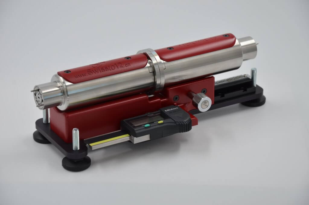
Figure 2 – SwissTo12 MCK
These systems measure the S-parameters, reflection, and transmission through the Material Under Test (MUT), and a mathematical inversion converts these measurements to a complex permittivity.
SPEAG’s Dielectric Assessment Kit (DAK) product line, based on the open coaxial probe method, provides high-precision dielectric parameter measurements (including permittivity, conductivity, and loss tangent) over a wide frequency range from 4 MHz to 67 GHz. The advanced hardware technology and user-friendly software of DAK instruments are designed for accurate, precise, and non-destructive measurements, making them ideal for use in telecommunications, material science, bioelectromagnetics, biomedical research, and industries like automotive, electronics, and food.
The DAK product line includes DAK-TL2, (Figure 4) the first system capable of measuring thin-layer materials and small liquid volumes, as well as DAK single probes and the DAK System (DAKS). DAKS is a low cost, portable, and easy-to-use dielectric assessment system kit that combines the DAK (Figure 3) technology with the miniature portable R60 and R140B vector reflectometers from Copper Mountain Technologies. The direct and rigid connection of the probe to the reflectometer allows the probe to be moved to the media under test after calibration, greatly simplifying measurements in the lab.
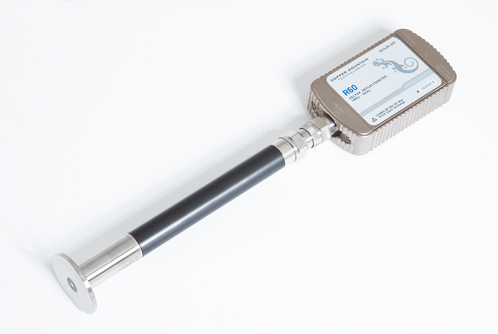
Figure 3 – SPEAG DAK Measurement System
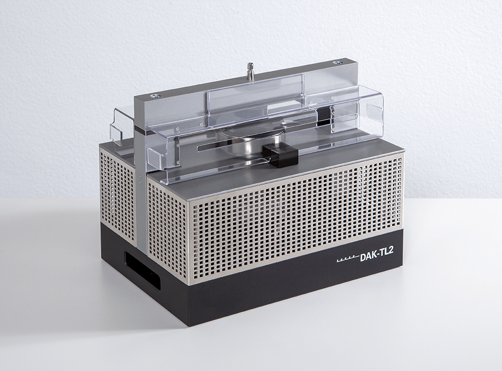
Figure 4 – DAK-TL2 Measurement System
How is the Permittivity Inversion Computation Done?
The computation is an inversion because the material’s complex permittivity determines the transmission and reflection of the RF waves. The inversion must solve for the unique permittivity that causes the measured reflections. Uniqueness is an important consideration. In any inversion problem, multiple parameter values could create the same outcome, so seeding the problem with a best-guess solution is usually necessary.
How is complex permittivity calculated from the S-Parameters? First, we model the transmission and reflection properties at the interfaces and within the material when illuminated by a plane wave.
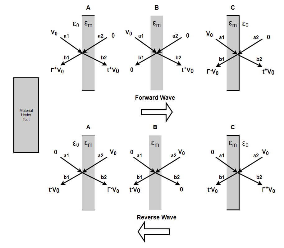
Figure 5 – Modeled Material Zones
As detailed by Dr. Schultz in [1] and shown in Figure 5, the MUT can be divided into three zones. A, an infinitely thin left-hand surface to model signal reflection; B, a central section to model signal transmission; and C, another infinitely thin surface to model a second reflection with a 180° phase shift compared to the first reflection. Reflections occur whenever a wave passes from a medium with one dielectric constant to another, ε0 to εm and εm back to ε0 in this case.
ε0, the permittivity of air is 8.854 x 10⁻¹² pF/m or may be normalized to 1.0. The material permittivity εm will be normalized by this value as well. For non-magnetic materials, the permeability μm can be set to 1.0.
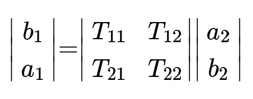
We could build S-Parameter matrices for the three zones, but Transfer parameters are more useful since they can be multiplied to obtain the composite result for the full slab of material.
Transfer Parameters relate the a and b terms thusly:
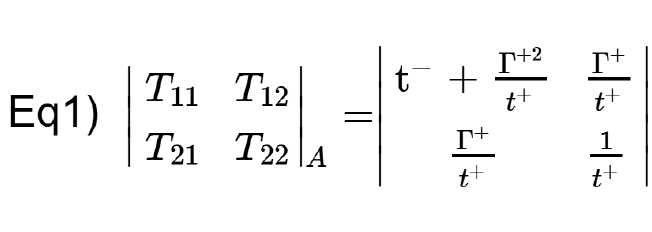
Filling in the values for a1, a2, b1, and b2 from the forward and reverse case of Zone A in Figure 3 and noting that Γ– = -Γ+, the four Transfer parameters can be solved:
The tangent voltages of the plane wave must be the same on each side of the interface for both forward and reverse waves. Substituting Γ– = -Γ+ and equating them:
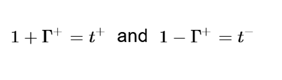
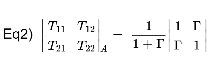
Eliminating the transmission parameters t+ and t–, The Transfer matrix for A can be written in terms of Γ+ alone. Dropping the “+” and doing the substitution:
The reflection at the interface is a known function of the normalized permittivity and permeability given by:
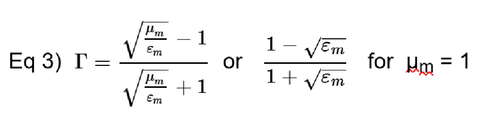
Note that if εm = 1 and μm = 1, then Γ = 0, or no reflection for an air-to-air interface.
From the forward and reverse wave cases for Zone B, the Transfer matrix can be determined:
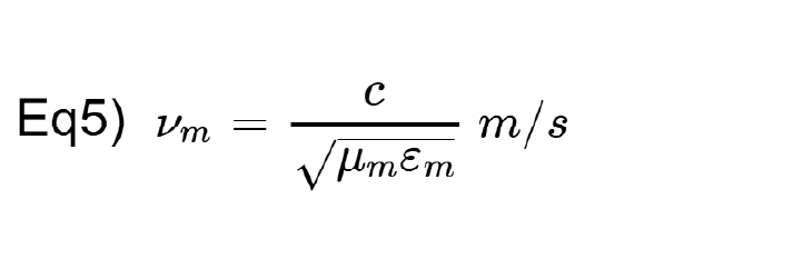
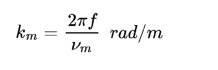
The propagation velocity of a wave is a function of the permittivity and permeability. For free space
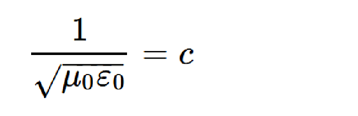
the speed of light. Using normalized εm and μm, the wave speed in the material under test is:
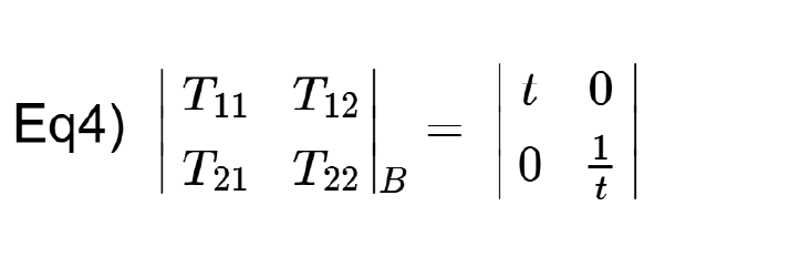
“t” in Equation 4 may be expressed in terms of the permittivity and permeability:
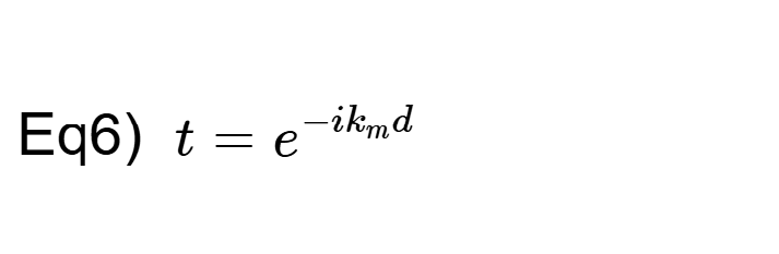
where material wave number
and d is the thickness of the material in meters. Finally, substituting -Γ for Γ into Equation 2 gives the Transfer parameters for Zone C:
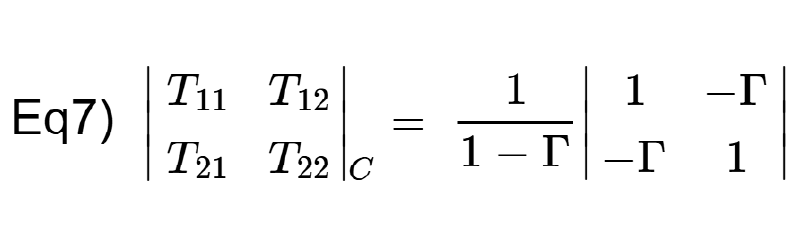
Multiplying all three matrices gives:
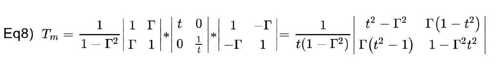
Finally, convert the Transfer parameters to S Parameters using the standard conversion formula and we get:
With that, we now have the S-Parameters in terms of εm and μm as measured from one surface of the MUT to the other. The Nicolson-Ross-Weir (NRW) algorithm [2,3] or an iterative solver can determine the permittivity and permeability that fits the measured data. In the free space methods, the NRW method is not recommended and a four-parameter method is preferred, since it eliminates the need to precisely position the sample under test.
For a non-magnetic sample, it is sufficient to measure S11 and S21, guess at the permittivity εm, calculate Γ and t, and then use an iterative method to improve the guess and minimize the errors in Equations 10 and 11:
As a sanity check, note that S21 = t if there is no reflection, Γ. Also S11 = Γ if there is no transmission, t.
After a potential solution is found, it is a good idea to plot the calculated vs measured values of S11 and S21 to assess the accuracy of the solution.
The primary issue with this method is that for materials with low loss-tangent, the imaginary part of εm is small, and changing its value has only a tiny effect on the complex value of S21. Most optimizer strategies will struggle with this problem. Compass Technologies, SwissTo12, and SPEAG have all overcome this issue with their software.
The equations detailed here provide a helpful background for an engineer who needs to perform material measurements. Integration experts at Compass Technologies, SwissTo12, and SPEAG provide measurement systems and software to perform these measurements and calculate permittivity. For a nominal fee, they can also make batch measurements for those who don’t wish to procure their own system.
Practical Considerations
Sometimes troublesome resonances may occur at frequencies where the sample thickness is an integer multiple of half wavelengths and measurements may contain singularities. This occurs when using both reflection and transmission inversions on non-magnetic specimens.
A video demonstrating the focused beam measurement is available here.
If TRL calibration is performed, it is helpful to normalize the S21 response while viewing it in the Smith Chart format. Place a marker in the middle of the frequency band. Move one of the antennas until a 90° phase shift is attained for the “Line” standard. For the “Thru” standard, move the antenna back until the phase is zero once again.
Time Domain Gating, a standard feature of all Copper Mountain Technologies VNAs (except the “M” series) should be applied to the area occupied by the MUT to eliminate multipath reflections from other surfaces in the lab.
Different material measurements require different solutions. Lower frequency measurements might be performed with a focused beam system from Compass Technologies. Liquid materials would best be measured with a system from SPEAG. mmWave measurements could be made with the MCK system from SwissTo12 or a table-top free-space measurement system from Compass.
The waveguide measurement fixture from SwissTo12 can measure plain, coated, or multilayer solids, liquids, and powders.
Conclusion
If you need to make material measurements like these, please contact Copper Mountain Technologies. Our sales associates and technical staff will help you find the best solution. Our metrology-grade VNAs cover frequencies from 1.5 to 330 GHz, and system integrators have the fixturing and expertise to get the job done.
Visit our website to see our VNA products and peruse helpful technical content, white papers, videos, and webinars that can help you make the best measurements possible with your test equipment.
References
- Schultz, J. W. (2023). Wideband Microwave Materials Characterization, Artech House, (1st ed., pp. 38-42).
- W. B. Weir, “Automatic measurement of complex dielectric constant and permeability at microwave frequencies,” in Proceedings of the IEEE, vol. 62, no. 1, pp. 33-36, Jan. 1974, doi: 10.1109/PROC.1974.9382.
- Vicente, A. N., Dip, G. M., & Junqueira, C. (2011). The step by step development of NRW method. SBMO/IEEE MTT-S International Microwave and Optoelectronics Conference (IMOC 2011). https://doi.org/10.1109/IMOC.2011.6169318
Learn more about VNA
Manufacturing Test for Automated Measurements