


Determining Resonator Q Factor from Return Loss Measurement Alone
June 23, 2020This article appeared in Microwaves & RF and has been published here with permission.
Determining Resonator Q Factor from Return Loss Measurement Alone
Written by Brian Walker, May 29, 2020
It is not uncommon to want to measure the Q factor of a resonator. This might be to determine its suitability for use in a coupled resonator filter or to evaluate the performance of an RFID tag. Generally, this measurement is made with very light input and output coupling to reduce the loading effect of the 50 ohm source and load impedances. Coupling to and from the resonator might be done with two electrically short antennas or loops to couple to the electric or magnetic fields of the resonator.
Figure 1 – Two port Q measurement
This measurement might be made with a Copper Mountain Technologies TR1300, 1.3 GHz Vector Network Analyzer (VNA). With its low cost and a frequency range which fits most resonator testing applications, it’s the perfect choice.
Figure 2 – TR1300/1 VNA from Copper Mountain Technologies
The S21 measurement obtained from light coupling is analyzed to extract the resonant frequency and Q-Factor of the resonator. The peak of the response is taken to be the resonant frequency and then two markers are placed 3 dB down from the peak value. The peak frequency divided by the 3 dB width of the peak is then equal to the Q-Factor.
For example, if this circuit is swept, one will obtain the measurement shown below.
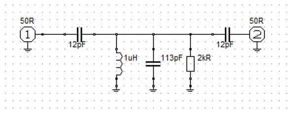
Figure 3 – Example circuit
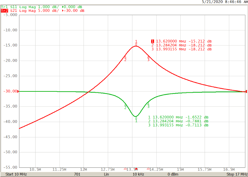
Figure 4 – 3 dB Q-Factor Measurement
The experimental Q-Factor from the graph is 13.62/(13.99-13.28) = 19.2
The approximate Q-Factor from the schematic, neglecting the effects of the 12 pF coupling capacitors and the 50 ohm source and load, is equal to the admittance of the 113 pF capacitor at 13.62 MHz divided by the conductance of the resistor or 9.673e-03/5e-04 = 19.3 so there is reasonable agreement. A slightly better measurement is possible if the coupling is reduced allowing the S21 peak to fall to -40 dB or so but the S11 reading would become very small. It will be shown that the Q-Factor may be derived from the S11 measurement, but the numbers need to be big enough to work with.
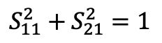
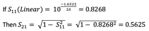
So how can this be done? It clearly isn’t a matter of looking for the points on the S11 curve that are 3 dB higher than the minimum. The trace shown above has a minimum of -1.6 dB so that is out of the question. It turns out that in a lossless circuit there is a relationship between S11 and S21, that is:
From the earlier graph we can calculate a value for :
This isn’t a real value per se but we can still use it. Calculating the value of which is 3 dB down means multiplying by
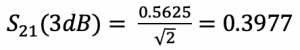
Now we take that back to

Or -0.748 dB
If we find this value of S11 on each side of the minimum from the earlier measurement we get this result:
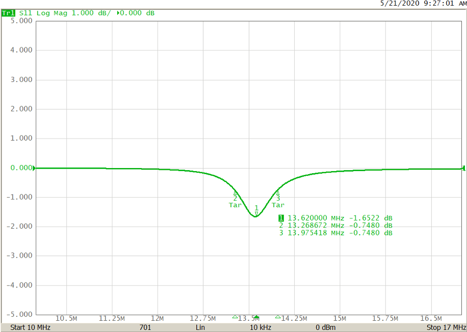
Figure 5 – S11 Measurement alone
And we can calculate the Q-Factor from these three frequencies:
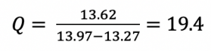
Which is pretty close to the calculated value of 19.3!
So with a fairly trivial calculation one can determine the Q-Factor of a resonator from a simple return loss measurement.