
CBRS Deployment and Optimization: Practical RF Challenges Solved with Low-Cost Vector Network Analysis
April 21, 2026
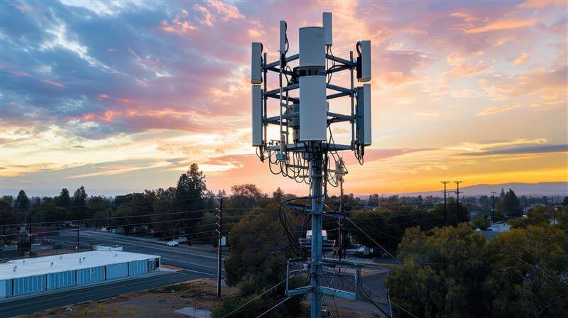
The Citizens Broadband Radio Service (CBRS) band from 3.55 to 3.7 GHz has rapidly become a cornerstone for private LTE and 5G deployments, enabling enterprises, utilities, campuses, and industrial operators to deploy localized wireless infrastructure with unprecedented flexibility. What was once the exclusive domain of carrier-grade RF engineering is now increasingly executed by system integrators, IT-centric teams, and field technicians, often under cost, time, and expertise constraints that differ substantially from traditional macro-network deployments.
As CBRS adoption accelerates, network performance is becoming tightly coupled to measurement quality. Coverage gaps, unstable throughput, elevated noise floor, and intermittent link behavior are frequently traced not to protocol or software issues, but to underlying RF impairments in the physical layer. In many practical deployments, small degradations in return loss, cable integrity, connector quality, grounding, or passive component behavior can materially impact system performance, particularly in dense or interference-sensitive environments.
This paper advances a practical thesis: a large fraction of CBRS performance problems are fundamentally RF problems, and many RF problems are, at their core, impedance and transmission problems. These impairments are directly measurable and diagnosable with a compact, low-cost vector network analyzer (VNA). By bringing accurate S-parameter measurement capability into the field at low cost and low complexity, deployment teams can identify, quantify, and correct RF issues early, significantly improving network reliability, predictability, and overall system performance.
Table of Contents
CBRS Technical Overview
Spectrum Structure
The CBRS band spans 3550 to 3700 MHz and is organized under a dynamic, tiered spectrum-sharing framework designed to maximize utilization while protecting critical users. At the top of this hierarchy is Incumbent Access, which includes U.S. Navy radar systems and certain fixed satellite service ground stations. These users receive absolute protection from interference and, when active, have priority over all other CBRS operations within affected geographic and frequency regions.
Below the incumbent tier is the Priority Access License (PAL) layer. PAL spectrum consists of licensed 10 MHz channels assigned on a county-by-county basis through auction. License holders receive interference protection from lower-tier users and gain predictable spectrum availability, making PAL suitable for applications requiring higher reliability, deterministic capacity, and controlled RF environments such as industrial private networks and critical infrastructure.
The third tier is General Authorized Access (GAA), which provides opportunistic use of any unoccupied CBRS spectrum not currently assigned to incumbents or PAL users. GAA enables low-cost entry and flexible deployment but operates without interference protection, meaning performance can vary depending on local spectrum demand and incumbent activity. Many enterprise and neutral-host CBRS networks rely heavily on GAA spectrum due to its accessibility and low barrier to entry.
Coordination among these tiers is managed by the Spectrum Access System (SAS), a cloud-based frequency management platform that dynamically assigns channels, enforces protection zones, and prevents harmful interference. The SAS continuously monitors spectrum usage and can reconfigure or revoke frequency assignments in near real time to maintain compliance with regulatory rules.
Supporting incumbent protection is the Environmental Sensing Capability (ESC), a distributed network of coastal RF sensors designed to detect incumbent naval radar activity. When radar is detected, the ESC informs the SAS, which then rapidly clears affected CBRS devices from the protected frequencies. Together, the SAS and ESC form the operational backbone of CBRS, enabling dynamic spectrum sharing while preserving reliable operation for both incumbent and commercial users.
CBRS Hardware Ecosystem
The CBRS hardware ecosystem is built around the Citizens Broadband Radio Service Device (CBSD), which serves as the radio node responsible for transmitting and receiving in the 3.55 to 3.7 GHz band under SAS control. CBSDs range from compact indoor enterprise units to higher power outdoor radios designed for wide-area or campus coverage. Regardless of form factor, these radios integrate baseband processing, RF transceivers, and control interfaces that coordinate frequency assignment, power limits, and operational status with the SAS.
Small cells and distributed antenna systems (DAS) play a central role in shaping coverage and capacity. Small cells are typically deployed to provide localized, high-quality service in offices, factories, campuses, and outdoor venues, while DAS architectures distribute RF energy through a network of remote antenna nodes to achieve uniform coverage in large buildings, stadiums, tunnels, or industrial environments. The choice between small cells and DAS is often driven by coverage geometry, user density, and installation constraints.
Deployment conditions vary significantly between outdoor and indoor environments. Outdoor systems must contend with propagation variability, weather exposure, grounding, and lightning protection, as well as longer RF cable runs and higher transmit power. Indoor deployments, by contrast, are often dominated by multipath, attenuation through building materials, and dense device environments that demand careful RF planning and interference management. These differing conditions influence hardware selection, antenna configuration, and infrastructure design.
Antenna systems in CBRS deployments are diverse and application dependent. Sector and panel antennas are commonly used in outdoor and point-to-sector coverage scenarios, while omnidirectional antennas support broad, uniform coverage in localized areas (in-building coverage). Modern CBRS networks frequently employ MIMO arrays to improve spectral efficiency, link robustness, and capacity through spatial diversity and beamforming. Antenna performance, polarization alignment, and impedance behavior directly influence system efficiency and coverage predictability.
Supporting all of these elements is the RF front end and cabling infrastructure, which includes connectors, coaxial cables, grounding systems, lightning protection devices, and passive components such as splitters, combiners, and filters. Loss, mismatch, shielding integrity, and installation quality within this physical layer often determine the real-world performance of a CBRS network. Even modest degradations in return loss or cable condition can translate into measurable reductions in coverage, throughput, and system stability, making the RF path a critical focus for measurement and optimization.
RF Performance Requirements
CBRS systems operating in the 3.5 GHz band place stringent demands on RF signal integrity, particularly as modern LTE and 5G waveforms rely on high-order modulation and tight spectral efficiency. Error Vector Magnitude (EVM) is highly sensitive to RF impairments such as mismatch, reflections, nonlinear distortion, and frequency-dependent loss. Even modest degradations in the RF path can increase constellation error, reduce modulation order, and ultimately degrade throughput and link stability. In practical deployments, intermittent reflections from poor connectors, damaged cables, or improperly terminated components often manifest as unstable performance rather than outright link failure, making these impairments difficult to diagnose without direct RF measurement.
Precise synchronization and low phase noise are also critical to CBRS network performance. Time and frequency alignment support coherent demodulation, MIMO operation, and spectrum coexistence, particularly in dense or interference-sensitive environments. Excess phase noise, local oscillator instability, or frequency-selective group delay variations in the RF chain can introduce symbol rotation, inter-carrier interference, and degraded receiver sensitivity. These effects are especially pronounced in wideband OFDM systems, where phase coherence across subcarriers is essential for maintaining link quality and predictable system behavior.
At 3.5 GHz, impedance integrity throughout the RF path becomes a primary determinant of system efficiency and stability. Mismatch between radios, cables, connectors, antennas, and passive components leads to reflections, standing waves, and frequency-selective ripple that directly impact transmitted and received signal quality. Unlike lower-frequency systems, where small impedance deviations may be tolerated, mid-band cellular operation is far less forgiving, and even moderate return loss degradation can translate into measurable performance loss. Maintaining controlled impedance across the entire transmission path is therefore fundamental to achieving consistent coverage, stable throughput, and reliable CBRS network operation.
Why RF Measurement Matters More in CBRS Than Traditional Cellular
In CBRS deployments, RF measurement assumes a more central role than in traditional cellular systems, largely because installations are frequently carried out by enterprise integrators, IT personnel, or field technicians rather than specialized RF engineers. While modern CBRS equipment is designed for ease of deployment, the underlying RF behavior remains governed by the same physical principles as carrier-grade systems. Subtle issues such as impedance mismatch, connector quality, and cable integrity can significantly influence performance, yet these effects are often invisible without proper RF measurement.
CBRS networks also tend to employ denser infrastructure with smaller cell radio, particularly in enterprise, industrial, and campus environments. As cell size decreases, the network becomes more sensitive to localized RF impairments, coverage irregularities, and small variations in antenna or feedline performance. In such architectures, minor degradations that might be tolerated in a large macrocell can materially affect link quality, handover stability, and overall network consistency.
Performance margins are further constrained by the shared-spectrum nature of CBRS. Unlike exclusive licensed spectrum, CBRS operation must coexist dynamically with other users, including PAL and GAA systems, as well as protected incumbents. This environment leaves less tolerance for inefficiencies in the RF path. Small degradations in return loss, insertion loss, or phase stability can reduce signal quality enough to expose the system to interference, reduce usable modulation order, or create unpredictable throughput behavior.
Interference sensitivity is therefore higher, both in terms of susceptibility to external signals and the potential to generate unintended emissions. Reflections, poor grounding, or degraded shielding can contribute to spectral regrowth, noise coupling, or unintended radiation, complicating coexistence and reducing network reliability. Accurate RF measurement allows these issues to be detected and corrected before they manifest as operational instability.
In practice, many real-world CBRS failures are not caused by software, protocol, or configuration errors, but by passive RF faults such as damaged cables, degraded connectors, poor terminations, or impedance discontinuities. These issues often produce subtle but consequential impairments that accumulate across the RF path. As a result, reliable CBRS deployment increasingly depends on the ability to measure, verify, and maintain RF integrity using practical and accessible tools such as compact vector network analyzers.
Common RF Problems in CBRS Deployments
Antenna System Issues
Antenna system performance is one of the most frequent sources of RF impairment in CBRS deployments, and small deviations from expected behavior can produce disproportionate effects on coverage and link stability. Poor return loss and impedance mismatch between the antenna and feedline lead to reflections that reduce radiated power, increase standing wave ratio, and introduce frequency-dependent ripple in the transmitted and received signals. At 3.5 GHz, even modest mismatch can measurably degrade effective isotropic radiated power and receiver sensitivity, directly impacting system throughput and reliability.
Antennas that perform well in isolation can become detuned after installation. Nearby conductive structures, mounting hardware, cable routing, and environmental factors alter the antenna’s boundary conditions and current distribution, shifting resonance and degrading impedance match. This detuning often occurs without obvious visual indication, yet it can significantly reduce radiation efficiency and distort the intended radiation pattern, producing localized coverage gaps or inconsistent link behavior.
Radomes and mounting configurations introduce additional electromagnetic effects that are frequently underestimated. Dielectric loading from radome materials, especially when combined with moisture, contamination, or aging, can shift resonance frequency and increase loss. Similarly, mounting surfaces and support structures can perturb the antenna near field, altering pattern symmetry, front-to-back ratio, and impedance characteristics. These effects are particularly relevant in compact installations where antennas are placed close to structural elements.
In MIMO-based CBRS systems, polarization integrity is critical for maintaining spatial diversity and achieving expected capacity gains. Polarization mismatch between antenna elements, or between the transmitter and receiver, reduces channel orthogonality and degrades signal-to-noise ratio. Misalignment during installation, mechanical drift, or unintended coupling between closely spaced elements can reduce MIMO effectiveness, leading to lower throughput and reduced link robustness. Accurate RF measurement of return loss, isolation, and impedance behavior provides a direct means of identifying and correcting these antenna-related impairments.
Cable and Connector Faults
Cable and connector integrity is a dominant factor in the real-world RF performance of CBRS deployments. Coaxial cables are often exposed to mechanical stress, environmental conditions, and installation variability that can degrade their electrical behavior over time. Physical damage, excessive bending, and repeated flexing alter the cable’s characteristic impedance and increase distributed loss, while moisture ingress introduces dielectric changes and additional attenuation. These effects are frequently gradual and may not produce an immediate failure, yet they can significantly reduce link margin and stability at 3.5 GHz.
Connector quality and installation technique are equally critical. Poorly manufactured connectors, worn mating surfaces, contamination, or improper torque introduce localized impedance discontinuities that generate reflections and increase return loss. Even small connector faults can produce measurable degradation in transmitted and received signal quality, particularly in systems with multiple interconnects where impairments accumulate along the RF path. In outdoor installations, corrosion and thermal cycling further exacerbate these discontinuities, leading to progressive performance decline.
One of the most characteristic signatures of cable and connector faults is reflection-induced ripple in the frequency response. Multiple reflections between impedance discontinuities form standing-wave patterns that create periodic amplitude variation across frequency, often accompanied by group delay distortion. These effects can degrade modulation fidelity, increase EVM, and introduce frequency-selective fading within the signal bandwidth. Because such impairments are not always apparent from simple power measurements, direct S-parameter characterization with a vector network analyzer provides an effective method for locating and diagnosing cable and connector-related faults before they compromise network reliability. The time-domain conversion function of a Vector Network Analyzer is extremely helpful for determining the location of offending reflections.
Passive Component Degradation
Passive RF components such as splitters, combiners, filters, and lightning arrestors are often assumed to be electrically transparent once installed, yet they can become significant sources of performance degradation over time. These devices introduce additional interfaces, internal transmission paths, and reactive structures that are sensitive to environmental stress and long-term material changes. While initial specifications may meet system requirements, real-world operating conditions frequently alter their electrical behavior in subtle but consequential ways.
Temperature variation and aging are primary drivers of passive component drift. Dielectric materials change permittivity with temperature, conductive surfaces oxidize, and mechanical interfaces relax under thermal cycling. In filters, these effects can shift passband characteristics and increase loss. In splitters and combiners, imbalance and port isolation may degrade. Lightning arrestors, which often rely on gas discharge or nonlinear protective structures, can accumulate wear from transient events, increasing insertion loss or introducing additional reflections even when no visible damage is present.
A particularly challenging aspect of passive degradation is the emergence of hidden insertion loss and localized impedance discontinuities. Small increases in loss may go unnoticed in power measurements but can reduce system link margin, especially in multi-stage RF paths. Likewise, impedance irregularities inside passive devices generate reflections that contribute to standing waves, frequency ripple, and phase distortion. Because these impairments are distributed and often masked by overall system behavior, direct measurement of transmission and reflection characteristics is essential for identifying degraded passive components before they produce measurable impact on CBRS network performance.
Site Interaction Effects
In practical CBRS deployments, antenna and RF system performance is strongly influenced by interaction with the physical installation environment. The ground plane and mounting structure form part of the electromagnetic boundary conditions seen by the antenna, and their geometry, conductivity, and proximity directly affect current distribution, radiation efficiency, and impedance behavior. Inadequate or unintended ground coupling can shift resonance, alter radiation pattern shape, and introduce additional loss, particularly in compact or irregular mounting configurations.
Nearby metallic structures are a frequent source of antenna detuning. Structural steel, cable trays, equipment enclosures, and support hardware can perturb the antenna near field, modifying both impedance and pattern. These effects may distort coverage, reduce front-to-back ratio, or introduce polarization changes, often without obvious physical indication. Because CBRS deployments commonly occur in dense industrial or enterprise environments, the likelihood of such interactions is high, and even small spatial changes can produce measurable RF variation at 3.5 GHz.
Multipath within the installation environment further complicates system behavior. Reflections from surrounding surfaces can combine coherently with the direct signal path, producing standing-wave-like behavior in both amplitude and phase across frequency and space. This can manifest as frequency ripple, localized fading, and group delay variation that degrade modulation quality and link stability. While multipath is often considered a propagation phenomenon, its effects frequently couple back into the antenna and feed system, making careful RF measurement and verification essential for distinguishing environmental interaction from hardware-related impairments.
Measurement Limitations in Typical CBRS Toolchains
Conventional CBRS field toolchains are primarily oriented toward power and signal presence, which limits their ability to diagnose underlying RF impairments. Spectrum analyzers, while indispensable for observing channel occupancy, interference, and emission levels, measure only power as a function of frequency. They provide no direct information about impedance behavior, reflections, or transmission integrity, leaving many physically rooted RF faults invisible.
Common cable and antenna testers improve basic verification but are frequently scalar instruments, reporting magnitude-only return loss or insertion loss without phase information. Without phase, it is difficult to distinguish between distributed loss and localized discontinuities, or to accurately identify the electrical distance to a fault. As a result, subtle impedance mismatches, partial cable damage, or multi-reflection conditions may go undetected or be misinterpreted.
Standalone return loss meters offer some insight into impedance match but typically lack the resolution and vector information required to localize problems or understand their frequency-dependent behavior. Without phase and time-domain capability, these instruments cannot reliably separate multiple reflections, evaluate group delay, or reveal standing-wave patterns caused by distributed impedance irregularities.
In practice, this leaves field technicians with limited visibility into the physical mechanisms degrading system performance. Tools may indicate reduced power, elevated noise, or poor throughput, yet provide little guidance on whether the root cause is mismatch, cable degradation, passive component drift, or environmental interaction. The central limitation is that most field instruments diagnose symptoms rather than root RF causes. Vector network analysis, by contrast, directly characterizes reflection, transmission, and phase behavior, enabling precise identification of the physical impairments that ultimately determine CBRS network reliability.
What a Low Cost VNA Brings to CBRS Engineering
Reflection Measurement (S11)
Reflection measurement, expressed as S11, provides a direct view into impedance behavior along the RF path and is one of the most informative diagnostics available in CBRS deployments. Measuring S11 at the installed antenna allows in situ verification of impedance match under real operating conditions, including the effects of mounting, nearby structures, radome loading, and environmental exposure. This eliminates the uncertainty associated with bench measurements and confirms whether the antenna is efficiently transferring power into free space at the intended frequency band.
S11 behavior across frequency also enables differentiation between antenna detuning and feedline faults. A smooth, frequency-shifted return loss curve often indicates antenna resonance displacement caused by environmental or mounting effects, whereas periodic ripple or broadband degradation typically points to cable or connector impairments. By analyzing the magnitude and phase of the reflection coefficient, these mechanisms can be distinguished with much greater confidence than with scalar measurements alone.
Applying a time domain transform to S11 further enhances diagnostic capability by converting frequency-domain reflection data into an electrical distance profile. This enables localization of impedance discontinuities such as damaged cables, poor connectors, or internal antenna faults. Distance-to-fault measurement is particularly valuable in CBRS installations with long or concealed feedlines, allowing technicians to identify and isolate physical problems without disassembling the entire RF path.
Transmission Measurement (S21)
Transmission measurement, expressed as S21, characterizes how efficiently RF energy propagates through a cable, component, or complete signal path and is essential for verifying integrity in CBRS installations. Measuring S21 across frequency reveals the true insertion loss of a cable under operating conditions, allowing detection of excess attenuation caused by physical damage, dielectric degradation, moisture ingress, or mechanical stress. Deviations from the expected loss profile, particularly frequency-dependent anomalies or localized notches, often indicate internal cable defects that are not apparent from visual inspection or simple continuity testing.
S21 is equally valuable for validating passive components such as splitters, combiners, filters, and lightning protection devices. These elements introduce predictable insertion loss and frequency response when functioning correctly, but aging, temperature exposure, or transient stress can alter their behavior. Transmission measurement allows confirmation that each component meets expected specifications and that port balance, passband shape, and attenuation remain within acceptable limits. This is particularly important in multi-stage RF paths where small degradations accumulate and reduce overall system margin.
A key advantage of vector transmission measurement is its ability to expose hidden insertion loss that may not be obvious in system-level power observations. Gradual increases in loss across cables or passive devices can quietly reduce effective radiated power and receiver sensitivity, leading to degraded throughput and unstable link behavior. By directly measuring S21, these losses can be quantified and localized, enabling corrective action before they materially impact CBRS network performance.
Phase and Group Delay
Phase and group delay measurements provide critical insight into the temporal behavior of the RF path, complementing magnitude-based diagnostics in CBRS systems. Variations in phase response across frequency often reveal multipath-induced ripple, where reflections within cables, connectors, or the surrounding environment combine with the primary signal to produce periodic phase distortion. These effects translate into frequency-selective delay variation that can degrade modulation fidelity, increase EVM, and introduce instability in wideband OFDM signals. Because multipath signatures frequently appear more clearly in phase and group delay than in magnitude alone, vector measurement is essential for identifying their origin.
Group delay consistency is particularly important in MIMO architectures, where multiple parallel RF chains must maintain coherent phase and timing relationships. Differences in electrical length, frequency-dependent dispersion, or localized impedance discontinuities can create delay skew between channels, reducing spatial orthogonality and degrading beamforming or diversity performance. Measuring phase and group delay across MIMO paths allows verification that each chain exhibits uniform transmission characteristics, ensuring predictable system behavior and preserving expected capacity gains.
These measurements also support verification of synchronization integrity. Accurate time and frequency alignment depend on stable phase response throughout the RF chain, and disturbances such as phase noise, dispersive components, or reflection-induced delay variation can compromise coherent demodulation and symbol timing. By examining phase linearity and group delay, engineers can detect subtle impairments that would otherwise manifest as degraded link stability, reduced modulation efficiency, or intermittent performance variation in CBRS networks.
Distance-to-Fault (DTF)
Distance-to-fault analysis converts frequency-domain reflection data into an electrical length profile, allowing precise localization of impedance discontinuities along the RF path. By examining the amplitude and position of reflected energy, DTF can identify the physical location of connector defects, moisture ingress, cable deformation, or crush damage that would otherwise be difficult to isolate. Even partial faults, such as a developing connector corrosion point or localized dielectric change from water intrusion, produce detectable reflections that can be resolved spatially along the transmission line.
In practical CBRS deployments, this capability significantly reduces diagnostic uncertainty and maintenance effort. Rather than relying on sequential disassembly, visual inspection, or repeated trial-and-error testing, technicians can directly determine where a fault exists and focus corrective action at the precise location. This minimizes unnecessary cable replacement, shortens troubleshooting time, and reduces repeated tower climbs or site visits. By eliminating guesswork, distance-to-fault measurement improves service efficiency while ensuring that underlying RF impairments are accurately identified and resolved.
Use Cases Where Low Cost VNAs Provide High Value
CBRS Site Installation and Commissioning
Effective CBRS deployment begins with verification that the RF path performs as intended before the radio is placed into service. Antenna tuning and validation are critical steps in this process. Measuring the installed antenna confirms that resonance, return loss, and impedance behavior remain within specification under real mounting and environmental conditions. This ensures that the antenna efficiently transfers power into free space, preserves the intended radiation pattern, and avoids reflection-induced degradation that could reduce coverage or increase EVM. Identifying detuning at this stage allows corrective adjustments to mounting, orientation, or hardware configuration before the system is activated.
Cable certification is equally important prior to radio activation. Verifying insertion loss, impedance uniformity, and reflection behavior across the full RF path ensures that feedlines and interconnects meet expected electrical performance. Detecting excess loss, connector faults, or developing moisture ingress early prevents hidden impairments from limiting effective radiated power or receiver sensitivity once the system is operational. By confirming RF integrity during installation and commissioning, deployment teams establish a stable physical layer foundation, reducing the likelihood of performance instability and minimizing costly post-deployment troubleshooting.
Troubleshooting Underperforming Cells
When a CBRS cell exhibits degraded throughput, unstable links, or inconsistent coverage, effective troubleshooting requires separating RF path impairments from interference or radio-related issues. Reflection and transmission measurements provide a direct method for distinguishing these mechanisms. Impedance mismatch typically manifests as elevated return loss, frequency ripple, and reduced power transfer, while passive path degradation appears as excess insertion loss or reflection signatures along the feedline. In contrast, true interference or radio faults often present without corresponding changes in the passive RF characteristics. By examining S-parameters, engineers can quickly determine whether the root cause lies in the transmission path, the RF environment, or the active radio hardware.
This capability enables rapid isolation of passive RF faults, which are among the most common causes of real-world CBRS performance degradation. Cable damage, connector defects, degraded passive components, and localized impedance discontinuities can be identified and localized without extensive disassembly or repeated trial-and-error testing. Once detected, corrective action can be focused precisely where needed, reducing downtime and avoiding unnecessary replacement of functional equipment. Systematic RF measurement, therefore, transforms troubleshooting from a process of symptom observation into one of physical diagnosis, allowing underperforming cells to be restored efficiently and with high confidence.
Preventive Maintenance
Preventive maintenance in CBRS systems relies on detecting subtle changes in the RF path before they evolve into observable performance degradation. Cables and connectors are subject to gradual wear from thermal cycling, mechanical stress, environmental exposure, and corrosion, all of which can slowly alter impedance and increase loss. These changes rarely produce immediate failure, but they reduce link margin and can eventually manifest as unstable throughput, increased EVM, or intermittent connectivity. Periodic RF measurement allows early identification of these trends, enabling corrective action before service quality is affected.
A particularly effective approach is comparison of current RF signatures against baseline measurements recorded at installation or commissioning. By tracking parameters such as return loss, insertion loss, phase response, and distance-to-fault profiles over time, even small deviations become visible. Emerging reflections, incremental loss increases, or shifting impedance characteristics can be detected and localized long before they produce system-level symptoms. This data-driven method transforms maintenance from reactive repair to predictive intervention, improving network reliability while reducing unplanned outages and costly emergency troubleshooting.
Manufacturing and Integration of CBRS Equipment
In the manufacturing and integration of CBRS equipment, consistent RF performance must be verified at multiple stages to ensure predictable behavior in the field. Antenna and RF module quality assurance is a primary focus, as small deviations in impedance match, gain, or frequency response can translate into measurable differences in coverage, efficiency, and EVM once deployed. Routine verification of return loss, isolation, and transmission characteristics helps identify assembly defects, material variation, or tuning drift before products leave the production environment.
Filter and duplexer verification is equally critical, particularly in systems operating within the tightly regulated CBRS band. These components must maintain precise passband shape, rejection, and insertion loss to ensure spectral compliance and minimize interference with adjacent channels or shared-spectrum users. Even minor shifts in resonance or increased loss can degrade receiver sensitivity or introduce unwanted emissions. Vector measurement enables confirmation that these devices meet design targets across frequency, temperature, and manufacturing variation.
Compact vector network analysis also supports practical production line testing without the need for high-cost, “showcase” instruments. By embedding calibrated, repeatable RF measurement directly into manufacturing workflows, engineers can rapidly validate impedance and transmission behavior, detect hidden faults, and ensure unit-to-unit consistency. This approach improves yield, reduces field failures, and enables high-confidence integration of CBRS radios, antennas, and RF subsystems while maintaining efficient production throughput.
How Lowering the Cost Contributes to Smoother Workflow
The economic and operational structure of CBRS deployments places a premium on accessible, widely deployable measurement capability rather than a single high-end showcase instrument. CBRS networks are inherently distributed, often spanning many small cells, indoor systems, and localized coverage zones. Ensuring consistent RF performance across numerous sites requires measurement at the point of installation and throughout the network lifecycle, which in turn demands multiple instruments rather than a centralized test resource.
In this context, portability, ease of use, and practical measurement capability often outweigh the need for extreme dynamic range of a large benchtop VNA. Field diagnostics typically focus on identifying mismatch, verifying transmission integrity, locating faults, and confirming component behavior, tasks that can be accomplished effectively with compact, well-calibrated vector measurement tools. The ability to deploy measurement directly at the antenna, feedline, or installed RF path provides far greater operational value than marginal improvements in measurement floor that are rarely required in real-world CBRS troubleshooting.
Low-cost instrumentation also enables RF measurement to be performed by field technicians and system integrators who may not have access to higher-end equipment. By lowering cost and complexity barriers, vector network analysis becomes a practical part of routine deployment, commissioning, and maintenance workflows rather than an occasional engineering exercise. This represents a broader shift toward measurement democratization, where RF visibility is moved out of the lab and into the field, allowing physical-layer impairments to be detected, understood, and corrected wherever they occur.
Practical Performance Requirements for CBRS VNAs
Vector network analyzers intended for CBRS field use must be aligned with the practical measurement demands of the 3.5 GHz band rather than laboratory extremes. At a minimum, frequency coverage should span roughly 3 to 4 GHz to fully encompass the CBRS allocation and allow margin for antenna resonance verification, cable characterization, and passive component evaluation near band edges. Adequate frequency resolution within this range is important for detecting narrow impedance features, ripple behavior, and subtle transmission anomalies that influence real-world performance.
Dynamic range requirements in CBRS applications are often more modest than in precision laboratory measurements. Most field tasks involve verifying return loss, identifying cable or connector faults, and measuring insertion loss of relatively short RF paths, conditions that rarely demand ultra-high dynamic range. Instead, measurement repeatability and stability are typically more valuable, particularly when comparing current measurements against installation baselines to detect gradual degradation.
Calibration robustness under field conditions is another key requirement. Instruments must maintain stable error correction despite temperature variation, mechanical handling, and repeated connection cycles. Reliable calibration enables consistent impedance and transmission measurements across different sites and over time, which is essential for troubleshooting and preventive maintenance workflows outside controlled laboratory environments.
Ruggedness and portability directly influence usability in CBRS deployments, where measurements may be performed at rooftops, towers, equipment rooms, or outdoor enclosures. Compact form factor, low power consumption, and resistance to environmental stress enable technicians to perform accurate RF diagnostics at the point of installation rather than transporting components back to a lab.
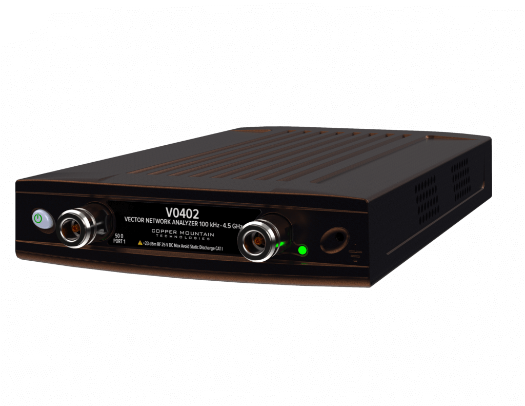
Figure 1 – Compact 4 GHz VNA
Finally, measurement speed must be balanced against frequency resolution and noise performance. Faster sweeps support efficient field operation and rapid troubleshooting, while sufficient resolution is required to identify reflections, ripple, and dispersion effects. Practical CBRS VNAs therefore prioritize a balanced architecture that delivers stable, repeatable measurements with adequate resolution and speed, optimized for diagnosing real-world RF impairments rather than achieving extreme laboratory specifications.
Limitations of Low Cost VNAs (and Why They’re Acceptable)
Low-cost vector network analyzers inevitably provide lower dynamic range than high-end laboratory instruments, which can limit their ability to measure extremely small reflections or very high isolation with metrology-grade precision. In applications that demand ultra-low noise floors, very high rejection measurement, or full device characterization across wide dynamic ranges, laboratory VNAs remain the appropriate tool. However, these extreme capabilities are rarely required in typical CBRS field environments.
In CBRS deployments, most performance degradation arises from relatively large, physically meaningful RF issues such as mismatch, excess insertion loss, reflection-induced ripple, or localized impedance discontinuities. These phenomena are well within the measurement capability of compact VNAs, enabling effective detection and localization without the need for laboratory-grade instrumentation. The practical value lies in identifying actionable problems rather than resolving minute electrical differences that have negligible impact on system behavior.
Ultimately, the distinction is one of engineering insight versus laboratory precision. Low-cost VNAs provide the visibility required to understand and correct the physical causes of RF performance degradation in deployed systems. While they do not replace high-end instruments for advanced research or metrology, they deliver the measurement capability that matters most for ensuring reliable CBRS operation in the field.
Future CBRS Market Outlook
Market forecasts vary by analyst and scope, but they are broadly consistent in showing strong, sustained double-digit growth for CBRS-driven private LTE and 5G systems over the coming decade.
Representative projections:
- The LTE/5G CBRS network market is expected to grow from roughly $1.9B in 2025 to about $13.6B by 2034, corresponding to ~24% CAGR.
- Another forecast places the CBRS and private LTE/5G market at ~20–21% CAGR through the early 2030s, reaching more than $12B by 2032.
- Broader private-network data, which is largely driven by CBRS in the U.S., shows similar expansion, with U.S. private LTE/5G networks growing at roughly ~24% CAGR to 2030.
Interpretation for CBRS specifically
- Growth is high but not exponential. Most credible estimates cluster around 20–25% CAGR.
- Expansion is driven primarily by private 5G, industrial wireless, neutral-host systems, and enterprise networks, many of which rely heavily on CBRS spectrum.
- Installed base growth is already significant, with hundreds of thousands of CBRS radios deployed supporting private cellular use cases.
The continued expansion of private 5G and neutral host networks is expected to further accelerate the adoption of CBRS-based infrastructure across enterprise, industrial, and public environments. As wireless connectivity becomes a foundational utility for automation, logistics, smart facilities, and mission-critical communications, the scale and geographic distribution of small-cell deployments will grow substantially. This evolution will place greater emphasis on maintaining consistent RF performance across large numbers of localized installations, many of which operate outside traditional carrier engineering frameworks.
With increasing RF density comes a corresponding rise in passive RF impairments. More antennas, cables, connectors, and passive components introduce additional points of failure and greater sensitivity to installation quality, environmental stress, and long-term material degradation. In dense mid-band systems, small impedance discontinuities and incremental loss can accumulate to produce measurable degradation in coverage, capacity, and link stability. As a result, passive RF problems are likely to become an even more dominant factor in real-world network reliability.
Low-cost vector network analyzers are well positioned to play a central role in this environment, particularly as diagnostics become more automated and remotely accessible. Compact instruments can be embedded into field workflows, maintenance kits, or even semi-permanent monitoring points, enabling continuous or on-demand verification of RF path integrity. This supports faster fault isolation, reduced maintenance overhead, and improved operational predictability across distributed network architectures.
Looking forward, integration with cloud-based monitoring platforms and predictive maintenance systems will further extend the value of vector measurement. By aggregating RF signatures over time, trends such as gradual impedance drift, increasing insertion loss, or emerging reflection points can be detected early and correlated with environmental or operational factors. This data-driven approach transforms RF maintenance from reactive troubleshooting to proactive network health management, improving reliability while reducing operational cost in next-generation CBRS and private 5G deployments.
Where CBRS Performance Failures Originate
A substantial portion of real-world CBRS performance failures originate not in software, configuration, or spectrum management, but in the physical RF infrastructure itself. Impedance discontinuities, excess insertion loss, degraded passive components, and installation-induced detuning frequently underlie symptoms such as unstable throughput, reduced coverage, and inconsistent link behavior. Without direct visibility into reflection and transmission characteristics, these physically rooted impairments are difficult to identify and often misattributed to higher-layer causes.
Maintaining clear insight into impedance and transmission behavior is therefore fundamental to reliable CBRS operation. Measurement of return loss, insertion loss, phase, and distance-to-fault enables engineers and technicians to diagnose the true electrical condition of antennas, cables, connectors, and passive components under real deployment conditions. This visibility transforms troubleshooting from symptom observation into physical diagnosis, allowing root causes to be identified and corrected with precision.
Low-cost vector network analyzers deliver this capability at the scale required by distributed CBRS deployments. While not intended for laboratory metrology, they provide the measurement performance necessary to detect the dominant RF impairments that affect practical network operation. Their portability, accessibility, and ease of use enable RF verification to move from centralized labs into routine field workflows, where it has the greatest operational impact.
By enabling practical RF measurement during installation, commissioning, troubleshooting, and maintenance, compact VNAs help reduce downtime, minimize unnecessary truck rolls, and lower deployment risk. The result is improved network reliability, greater predictability, and more efficient operation across the growing ecosystem of CBRS and private 5G systems.
Copper Mountain Technologies produces a wide range of Vector Network Analyzers and accessories. Compact VNAs are available with top ends of 1.5 to 18 GHz. Feel free to visit out website to find the VNA which perfectly fits your application and contact your sales representative for a product demo.
Learn more about the VNA

Manufacturing Test for Automated Measurements