The Calibration Wizard allows to create and customize various calibration configurations. It is possible to create multiple configurations and perform calibration later by simply selecting the desired configuration from the list.
The configuration is used to combine ports into a group and assign a calibration type to that group. You can create several port groups in a single configuration and assign the required calibration types to them. For example, Port 1 can be combined into group 1. This group can be assigned to the Reflection Normalization (Response Open) calibration type. Then, Port 2 and Port 3 can be combined into group 2, and this group can be assigned Full one-port (SOL) calibration type. Next, Port 4, Port 5, Port 6 and Port 7 can be combined into group 3, and this group can be assigned another type of ACM calibration and so on.
Once ports have been grouped together, set the calibration plane parameters for all groups by selecting the connector type and connector gender for each port, as well as the calibration kit or ACM used in calibration. Then, perform the calibration step-by-step.
note |
Each port can only be used in one group. If necessary, ports can be rearranged. |
note |
The Calibration Wizard does not allow to create S-parameter calibrations and power/receiver calibrations in the same configuration. Power/receiver calibrations should be done in a separate configuration. |
The Calibration Wizard pop-up window is shown in the figure below. The window contains a configuration list with the created configurations and a configuration area for customization of calibration configuration. You can click on areas or labels in the figure to go to a description of the wizard parts.
.
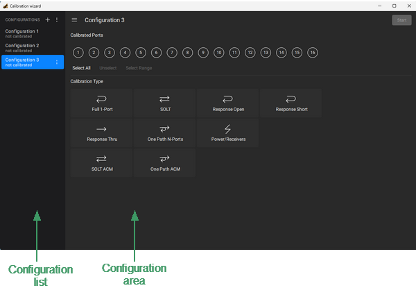
Calibration Wizard Pop-up Window
The sequence of actions to perform calibration in the wizard:
1.Run Calibration Wizard (see Starting Calibration Wizard Pop-up Window).
2.Create a configuration (see Adding New Configuration) or use an existing configuration (see Editing a Configuration).
3.If creating a new configuration: create port groups and assign each group the required calibration type (see Creating a New Ports Group).
4.If creating a new configuration: select a calibration plane for each port involved in the calibration (see Selecting Calibration Plane). Calibration plane must be selected in accordance with the connectors of the measured DUT.
5.Run the configuration (see Starting Configuration).
6.Complete calibration steps.
7.Apply a configuration (see Applying a Configuration).
For a detailed description of each calibration type and step-by-step execution of the calibration procedure, see Calibrations Step-by-Step.
Starting Calibration Wizard Pop-up Window
|
Select the channel (see Selection of Active Trace, Diagram, Channel) and set the parameters of the channel (frequency range, IF bandwidth, etc). |
|
If calibration is performed using the calibration kit, make sure required calibration kit is marked as AVAILABLE in Calibration Kits Management. If the calibration kit is missing, add the kit and its description. |
|
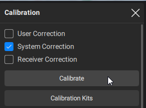
Click on the Calibration > Calibrate buttons in the sidebar.
|


|