After assigning a group, it is necessary to configure the calibration plane of the ports in the groups. The configuration is performed in the CALIBRATION PLANE tab in Configuration Area (see figure below). The plane settings to be defined depend on the selected calibration (see table below).
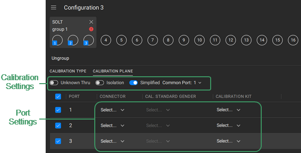
Example of Calibration Plane Definition Tab
Calibration Plane Settings
Calibration Type |
Calibration Settings |
Port Settings |
|---|---|---|
Reflection Normalization (RO or RS) |
LOAD standard |
Connector type Connector gender Calibration kit |
Source Port |
||
— |
||
|
|
|
|
|
|
|
|
|
If multiple port groups are created in the Calibrated Ports area in the configuration, click on the required ports group tab (see Grouping Ports).
|
|
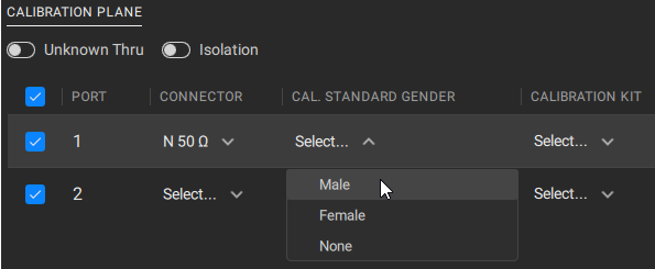
For each port in the group, click on the fields in the table and set the desired port parameters, as well as the calibration parameters in the CALIBRATION PLANE tab. For example, for a full two-port calibration (SOLT) using the calibration kit, select the desired connector type and gender, as well as the calibration kit, and if necessary, enable an unknown thru and isolation. For power calibration, select a power meter and set the loss parameters, if necessary. For a detailed description of the parameters required to set the calibration plane, refer to the description of each calibration type in Calibration Wizard.
|
|
If several port groups are created, then switching between groups, configure the calibration planes in each group. NOTE If the calibration plane of at least one port is not configured, then the configuration cannot be run. |


|
note |
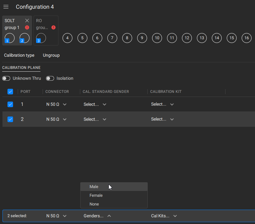
You can install parameter to several ports at the same time: •Select the checkboxes in the corresponding rows in a table. A line will then appear at the bottom of the table to change the parameter group. •Click on the parameter and select the desired value from the drop-down list.
|
note |
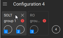
The wizard automatically checks if the selected port connector type and gender match the calibration kit standard, or if no calibration type is selected in Power/Receiver calibration. If there is a discrepancy, e.g. there is no suitable standard in the calibration kit, the A duplicate icon appears near the corresponding line in table. |
 icon will appear next to the group name. Hover the mouse over the icon to see where the discrepancies occur. The calibration procedure cannot begin if there are any discrepancy messages present.