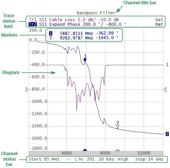
The channel windows display the measurement results in the form of traces and numerical values. The screen can display simultaneously up to 4 channel windows for RVNA and up to 16 channel windows for RNVNA. The analyzer hardware processes channels sequentially.
In turn, each channel window can display up to 4 traces of the measured parameters for RVNA and up to 16 trace of the measured parameters for RNVNA. If there is more than one trace in a channel window, the way they are displayed can be changed in the diagram (See Trace Layout in the Channel Window).
The general view of the channel window is represented in figure below.
Channel window
Each channel window contains a Channel title (hidden by default) to be defined by the user, Trace status field to display the name and parameters of the traces, Diagram for displaying traces, as well as information about the channel status in the form of the Channel Status Bar. To display the measurement values at the indicated trace points, use the Markers feature.
Each window has the following parameters:
•Stimulus signal settings:
•IF Bandwidth and average
Note |
The calibration parameters are applied to the whole the Analyzer and affect all the channel windows. |
