A model of a calibration standard presented as an equivalent circuit is used for determining the S-parameters of the standard. The model is employed for OPEN, SHORT, LOAD, THRU/DELAY standard types.
The one-port model is used for OPEN, SHORT and LOAD (see Full One-Port Calibration) standards. This is shown in the figure below.
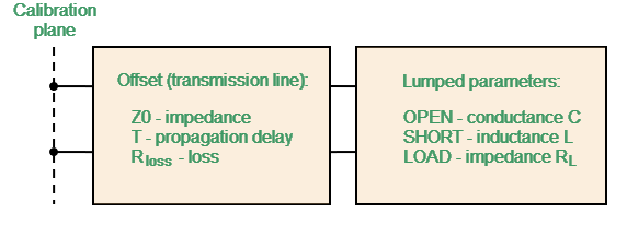
One-Port Standard Model
The two-port model is used for THRU and DELAY standards (see figure below).
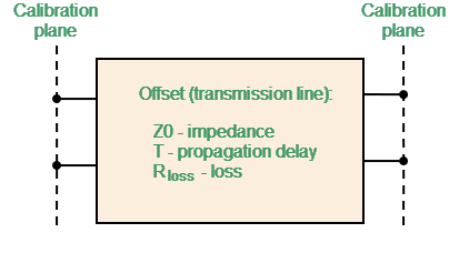
Two-Port Standard Model
Standards Definition Sidebar for the Standards Defined by the Circuit Model
The description of the Standards Definition Sidebar of a calibration standard defined by an equivalent circuit model is shown in the table below.
Field (as in the software) |
Field Definition |
|---|---|
Label |
Standard label |
Type |
The standard type (see Types of Calibration Standards) |
Definition |
The Analyzer supports two methods for defining a standard: •Databased (The calibration standards defined by S-parameters are called Databased standards). |
Connector |
The type of standard connector (see Editing User-Defined Connector Type) |
Gender |
The gender of a coaxial standard: •Male •Female |
The minimum and maximum standard operating frequency in the coaxial. Used for calibration that uses several calibration standards, each of which does not cover entire frequency range.The measurements of the standards outside the specified frequency range are ignored in the process of calibration. |
|
The waveguide width and height. Used in the waveguide loss model when the loss value is not zero. |
|
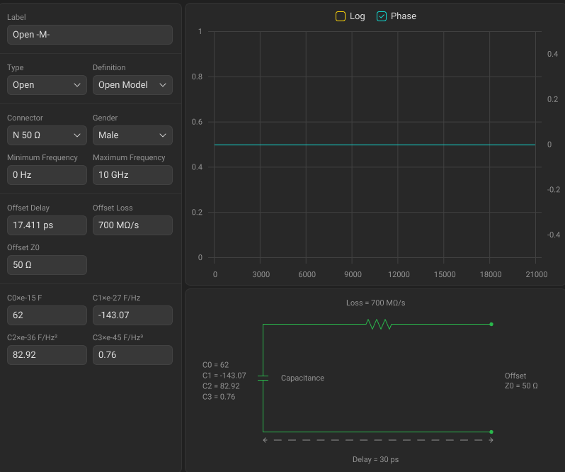
The offset delay. It is defined as one-way signal propagation time in the transmission line. Unit: [seconds]. The delay can be measured or mathematically determined by dividing the exact physical length by the propagation velocity in the line. For waveguide, delay is conventionally taken to be equal to the delay of a coaxial line of the same length. The actual signal delay in waveguide is frequency-dependent and is calculated in the software. Instead of delay, you can specify the length of the offset. Unit: [meters]. The software calculates the delay according to the formula for a coaxial air line: , where — line length [m], — light speed in free space 299792458 [m/s], — relative permittivity of air 1.000649. The offset delay can be switched to the physical length [m] (see Selecting Offset Units). The length can be specified instead of the delay, provided that the offset of the calibration standard is a coaxial airline or a waveguide. If the calibration standard manufacturer provides delay data, specify delay. |
|
The offset loss in one-way propagation due to the skin effect. Unit: [Ω/sec]: •The loss in the coaxial transmission line is determined by measuring the delay T [sec] and loss L [dB] at a frequency of 1 GHz. The measured values are used in the following formula:
•The loss in waveguide is typically set to 0 due to its very small influence. However, the software supports a waveguide loss model. If the calibration standard manufacturer provides loss data, specify it. |
|
The characteristic impedance of the transmission line, serving as the offset. Unit: [Ω]. For the coaxial line specified real value of characteristic impedance, usually equal to 50 Ω or 75 Ω. NOte Z0 of the selected connector type is installed by default. |
|
|
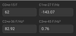
(C0, C1, C2, C3) |
The fringe capacitance of an OPEN standard, which causes a phase offset of the reflection coefficient at high frequencies. The fringe capacitance model is described as a function of frequency, which is a polynomial of the third degree: , where — frequency [Hz], C0…C3 — polynomial coefficients. Units: C0[F], C1[F/Hz], C2[F/Hz2], C3[F/Hz3]. |
|
(L0, L1, L2, L3) |
The residual inductance of a SHORT standard, which causes a phase offset of the reflection coefficient at high frequencies. The residual inductance model is described as a function of frequency, which is a polynomial of the third degree: , where — frequency [Hz], L0…L3 — polynomial coefficients. Units: L0[H], L1[H/Hz], L2[H/Hz2], L3[H/Hz3]. |
Load impedance of a fixed load calibration standard. Unit: [Ω]. For the coaxial calibration standard specified real value of characteristic impedance, usually equal to 50 Ω or 75 Ω. |
Editing Standard Label
|
Select the desired standard in the Standards List by clicking on it. Note If there are no suitable standards, you can add a new standard (see Adding New Standard to Calibration Kit). |
|
Click the Label textbox in the Standards Definition Sidebar and enter the standard label.
|


|
note |
It is recommended to mark gender in Label textbox (see Gender of Calibration Standard). |
Selecting Standard Type and Circuit Model Definition
|
Click the Type drop-down list in the Standards Definition Sidebar, and select standard type. |
|
Click the Definition drop-down list in the Standards Definition Sidebar, and select: •Open Model for Open standard type. •Short Model for Short standard type. •Matched, Sliding Load, or Arbitrary for Load standard type. •Thru Model for Thru standard type. •Line for Line standard type.
|

|
Selecting Standard Port Connector and Gender
|
Click the Connector (Connector 1 and Connector 2 for two-port standard only) drop-down list in the Standards Definition Sidebar, and select connector type. Note The drop-down list contains connectors from the Connectors Library. |
|
Click the Gender (Gender 1 and Gender 2 for two-port standard only) drop-down list in the Standards Definition Sidebar, and select connector gender. Note For coaxial gendered media only.
|

|
Editing Standard Minimum Frequency and Maximum Frequency
|
Click the required textbox in the Standards Definition Sidebar, and enter the numerical value. NOTE Editing minimum frequency and maximum frequency of the standard is usually not required, because it is set according to the selected connector.
|
|
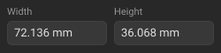
Editing Waveguide Standard Width and Height
|
Click the Width and Height textboxes in the Standards Definition Sidebar, and enter the numerical value. NOTE For standards with waveguide media only. Editing width and height of the standard is usually not required, because it is set according to the selected connector.
|
|
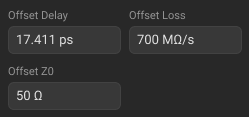
Editing Offset Delay, Offset Loss, Offset Z0
|
Click the Offset Delay and Offset Loss textboxes in the Standards Definition Sidebar, and enter the numerical value. |
|
Click the Offset Z0 textbox in the Standards Definition Sidebar, and enter the numerical value. NOTE For coaxial media only. Editing offset Z0 impedance of the standard is usually not required, because it is set according to the selected connector.
|
|
Editing Standard Capacitance, Inductance, or Arbitrary Impedance
|
Click the required textbox in the Standards Definition Sidebar and enter the numerical value.
|
|
Back to Calibration Kits Management
|
Click on the calibration kit title at the top of the window.
|

|