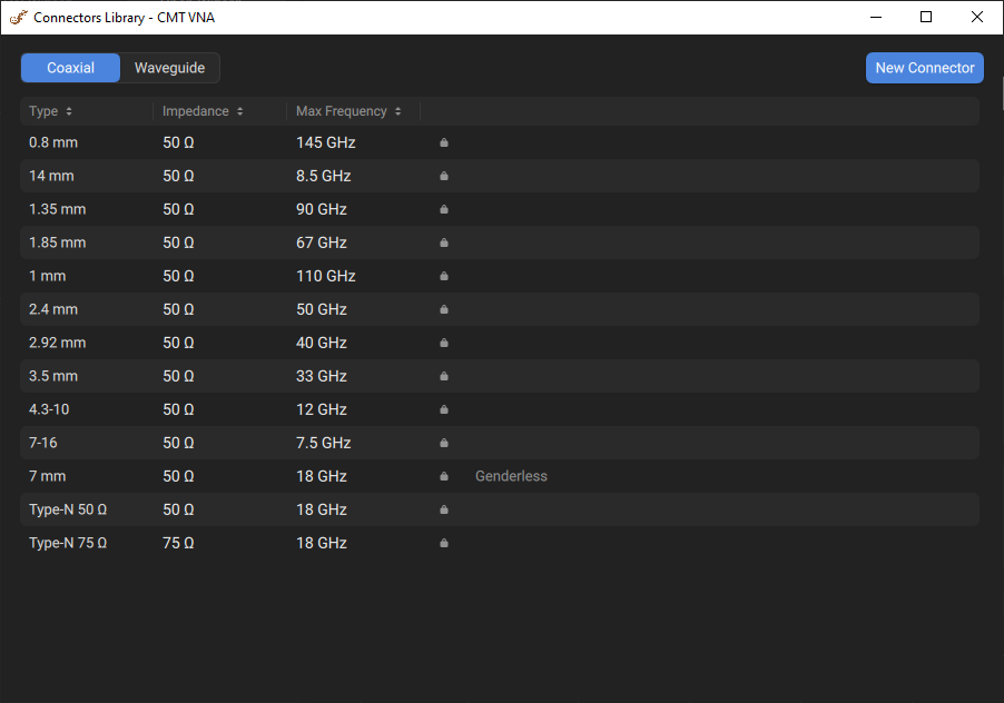
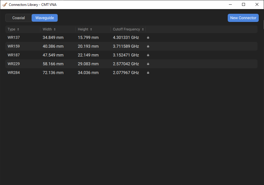
The Edit Connectors pop-up window displays a table of available connector types in the software. Connectors are grouped by the offset media type: coaxial and waveguide (see figures below).
Before measurements, ensure that the selected connector types match the connectors of the DUT.
By default, the table contains predefined connectors whose parameters cannot be modified. You can add a new user-defined connector. Editing and deleting functions are only available for user-defined connectors.
Coaxial Connectors Table |
Waveguide Connectors Table |
The tables below describe the columns in the connectors table.
Columns of the Coaxial Connector Table
Column |
Description |
|---|---|
Connector type name. |
|
Impedance |
The characteristic impedance for the coaxial connector. Value has an impact on various parameter conversions. For example, the impedance enters into the calculation of the S-parameters for the calibration standards, if they are derived from a circuit model. The calculation of the (default) reference impedances for balanced ports. |
Max Freqency |
The maximum operating frequency of the coaxial connector, which is usually specified by the manufacturer with a margin relative to the maximum frequency. |
Icon |
An icon representing the predefined connector. |
Status Genderless |
Indicates if a coaxial connector is genderless; this status is displayed in the corresponding row of the table. |

Columns of the Waveguide Connector Table
Column |
Description |
|---|---|
Connector type name. |
|
Width |
The waveguide width. |
Height |
The waveguide height. Used in the waveguide loss model when the loss value is not zero. |
Cutoff Frequency |
The cutoff frequency of the waveguide. The cutoff frequency of the waveguide is achieved at a wavelength in the waveguide equal to twice its width. Note that this is different from the minimum and maximum operating frequency of the waveguide, which are usually specified by the manufacturer with a margin relative to the cutoff frequency. |
Icon |
An icon representing the predefined connector. |
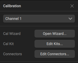
Starting Connectors Pop-up Window
|
Click the Calibration > Edit Connectors buttons in the sidebar.
|

|
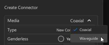
Adding New User-Defined Connector
New connector is added to the end of the table.
|
Click the New Connector button in the Connectors pop-up window.
|
|
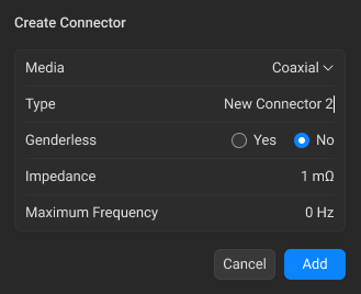
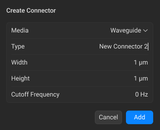
Select media between Coaxial and Waveguide from the drop-down list in the Media field in the Create Connector pop-up window.
|
|
When Coaxial media is selected: •Click the Type field and enter the connector type name. •Adjust Genderless: If the connector is genderless, click the Yes radio button in the Genderless field. Note The corresponding status will appear to the right of the selected connector:
If the connector is gendered, click the No radio button in the Genderless field (default). Note For the gendered connector, it is necessary to specify the gender (male/female) in the Standards pop-up window (see Standard Definition). •Click the Impedance field and enter the impedance value. •Click the Maximum Frequency field and enter the maximum frequency value at which the connector operates.
note If zero values are entered for impedance or maximum frequency, the status "Invalid" appears in the corresponding row.
|
|
When Waveguide media is selected: •Click the Type field and enter the connector type name. •Click the Width field and enter the waveguide width value. •Click the Height field and enter the waveguide height value. •Click the Cutoff Frequency and enter the cutoff frequency value of the waveguide.
|
|
Click the Add button. |


|
Editing User-Defined Connector
User-defined connectors can be edited. This function is not available for predefined connectors.
|
Click the horizontal-ellipsis button
|
|
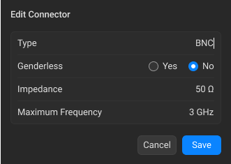
When Coaxial media is selected: •Click the Type field and edit the connector type name. •Adjust Genderless: If changing connector to genderless, select Yes in the Genderless field. Note The corresponding status will appear to the right of the selected connector:
If changing connector to gendered, select No in the Genderless field. Note For the gendered connector, it is necessary to specify the gender (male/female) in the Standards pop-up window (see Standard Definition). •Click the Impedance field and edit the impedance value. •Click the Maximum Frequency field and edit the maximum frequency value at which the connector operates.
Note For the gendered connector, it is necessary to specify the gender (male/female) in the Standards pop-up window (see Standard Definition). |
|
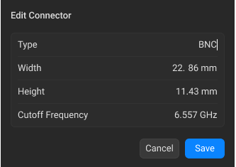
When Waveguide media is selected: •Click the Type field and edit the connector type name. •Click the Width field and edit the waveguide width value. •Click the Height field and edit the waveguide height value. •Click the Cutoff Frequency and edit the cutoff frequency value of the waveguide.
|
|
Click the Save button. |

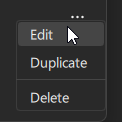

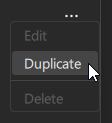
Duplicating Connectors
You can duplicate both predefined and user-defined connectors. In this case, duplicated predefined connector loses its status and can be modified, if necessary.
|
Click the horizontal-ellipsis button
|
|
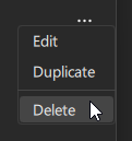
Deleting User-Defined Connector
User-defined connectors can be deleted. This function is not available for predefined connectors.
|
Click the horizontal-ellipsis button
|
|
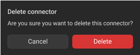
Click the Delete button in the opened dialog window.
|
|
note |
If you delete the connector used in the User-Defined calibration kits, all kits will replace this type of connector with the first one in the table (N 50 Ω). |