The Standards window provides detailed information about each standard included in the selected calibration kit (see figure below). This window contains the following areas:
Standards List – Displays a list of all standards available in the calibration kit.
Standards Definition Sidebar – Provides options for defining each standard (see Standards Definition). For predefined kits, the parameters are view-only.
Diagram Area – This area automatically generates a graph based on the parameters in the Standards Definition Sidebar, displaying characteristics such as Log and Phase.
Equivalent Circuit Model (for circuit model standards only) – Located below the diagram, this area shows an equivalent circuit model. The values for capacitance, inductance, or arbitrary impedance are derived from the corresponding parameters in the Standards Definition Sidebar, providing a visual representation of the standard’s circuit characteristics.
To open the Standards window, double-click on the desired calibration kit row in the Calibration Kits window (see Calibration Kit Management). The name of the active calibration kit is displayed in the title bar at the top of the window.
For user-defined calibration kits, you can add, edit, or delete standards. These functions are not available for predefined calibration kits.

Standards Window
The instructions below cover managing standards in the Standards List. For detailed information about defining and editing standards, see Standards Definition for general information, Circuit Model Standards Definition for circuit model standards or Data-Based Standards Definition for data-based standards.
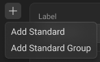
Adding New Standard to Calibration Kit
|
Click the Add Standard icon
|


|
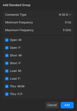
Adding Standard Group to Calibration Kit
This function allows you to add a group of standards with specified connector type and frequency range. These parameters will apply to all standards added in this group.
|
Click the Add Standard icon
|
|
In the Add Standard Group dialogue window: •Select the desired connector type from the Connector Type drop-down list. Note The drop-down list contains connectors from the Connectors Library. •Enter the frequency range in the Minimum Frequency and Maximum Frequency fields.
|
|
In the list of standards, use the checkboxes to select which standards to include in the calibration kit. note All checkboxes are selected by default. |
|
Click Add. |


|
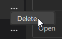
Deleting Standard from Calibration Kit
|
Click the horizontal-ellipsis button
|
|
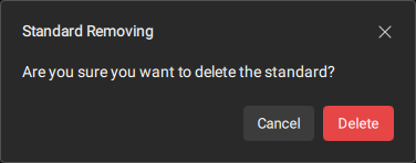
Click the Delete button in the opened dialog.
|

|
Back to Calibration Kits Management
|
Click on the calibration kit title at the top of the window.
|

|