The second step Fixture connection allows to select measurement patterns, as well as assigning ports between the Analyzer and the fixture (See figure below).
The selected configurations will be measured in the Fixture measurement tab. The number of measurement steps will correspond to the number of configurations.
Warning |
The plug-in tracks errors related to incorrect actions or calculations. Remember that with a Critical error Calculation errors and status messages about saving and loading files, or about setting default plug-in parameters, are displayed in the Notification Panel. |

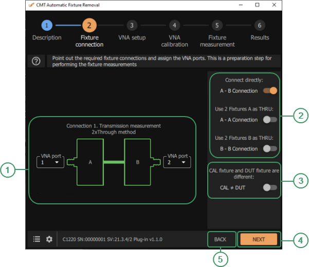
Fixture connection
|
|
Analyzer Ports Area Select the Analyzer port from the drop-down list. |
|
|
Connection Checkboxes Select the appropriate measurement configuration: A-B, A-A, or В-В. |
|
|
CAL ≠ DUT Checkbox Use the CAL ≠ DUT mode if the DUT is installed in a fixture or is structurally implemented in a fixture where there is no possibility to remove it. CAUTION. The CAL ≠ DUT mode is available only when the time gating method is selected. |
|
|
NEXT Button Click this button to move to the next step. |
|
|
BACK Button Click this button to return to the previous step. |


Instruction
1.Use options A-B, A-A, or В-В to select the appropriate measurement configuration. The plug-in will automatically display the selected configuration on the screen. The ON state for the configuration corresponds to 2xThrough, and the OFF state to 1xReflect.
The A-B configuration is used when using fixtures close in topology and length, located along the input and output of the DUT.
The A-A configuration is used if there are two identical input fixtures A that can be connected to each other. The auxiliary fixture is shown in the A Aux figure.
The B-B configuration is used if there are two identical output fixtures B that can be connected to each other. The auxiliary fixture is shown in the B Aux figure.
The A-A and B-B configurations allow thru measurement, if fixture A and B are fundamentally different.
If a THRU connection is not possible, the fixture parameters will be determined by 1xReflect, i.e. in open or short circuit mode.
2.The plug-in offers to use the CAL ≠ DUT mode if the DUT is installed in a fixture or is structurally implemented in a fixture where there is no possibility to remove it. In this case, two measurements are taken: (1) the calibration fixture without the DUT and (2) the test fixture with the DUT installed. These two fixtures should be identical. The joint processing of measurements will allow to obtain more reliable parameters of the investigated fixture without disconnecting the DUT. Note that if the calibration and test fixtures differ, especially in length, then the result of joint measurements will be invalid. The results, in graphical form, can be viewed in Fixture measurement / Edit characterization.
The CAL ≠ DUT mode is available only when the time gating method is selected.
3.After selecting a measurement configuration, assign the Analyzer ports. Select the Analyzer port from the drop-down list.