Fixture measurement guides fixture measurement and calculation of its S-parameters.
The calculated S-parameters will be loaded into the analyzer as *.S2P files. One Analyzer port equals one fixture description file. Note that parameters of the fixture marked Aux are not sent to the Analyzer software.
The number of measurement steps will correspond to the number of configurations selected in Fixture connection.
Go through the plug-in measurement steps sequentially.
There are two methods for determining fixture parameters:
•1xReflect. Full reflection of the fixture at the connection point of the DUT. Reflection in open and/or short circuit mode.
•2xThrough. Thru measurement of two connected fixtures.
Warning |
The plug-in tracks errors related to incorrect actions or calculations. Remember that with a Critical error icon Calculation errors and status messages about saving and loading files, or about setting default plug-in parameters, are displayed in the Notification Panel. |

Fixture measurement
|
|
Click this button to load previously measured standard data from a Touchstone file (*.SNP). |
|
|
Measure Button Click this button to perform measurements. |
|
|
Edit characterization Button Click this button to view plots of the results. |
|
|
NEXT Button Click this button to continue to the next step. |
|
|
BACK Button Click this button to return to the previous step. |


CAUTION |
Also see possible Messages. |
Instruction
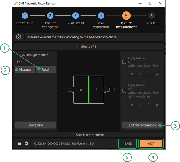
Procedure for 2xThrough
•Connect the fixtures that have two identical halves connected to each other to the calibrated Analyzer.
The plug-in displays the Analyzer ports for fixture connection, as well as the status of the current calibration.
•Click Measure button to take measurements or click Recall button to load a file and calculate from previously saved data.
The S-parameters of the fixture, the frequency grid, and the impedance value at which the data were obtained are read from the file. Here, the S-parameters of the fixture are the parameters measured on the calibrated Analyzer without performing additional calculations. These are the raw parameters. The calculations are performed using the frequency grid from the file. If the frequency grid does not match the current parameters, the data will be interpolated when further loaded into the Analyzer.
After the calculation, the plug-in displays key information on the screen: Analyzer port number, Analyzer system impedance, fixture electrical length, fixture impedance (low pass mode), together with the impedance selected for conversion.
The results of the fixture calculation can be viewed by clicking Edit characterization button.
To delete the measured data, click on the Delete data button.
2xThrough – returns the S-parameters of two fixtures with the same transmission coefficients and different reflection coefficients. The parity of the transmission coefficients shows that after applying the calculation results, the Analyzer calibration plane will pass exactly in the middle of the two connected fixtures. If necessary, the plug-in allows for adjustment of the electrical length of each of them. Two options are provided for this: (1) manual input of the offset or (2) automatic determination of the offset using the result of the reflection coefficient measurements of each fixture in open and/or short circuit mode. To perform measurements according to option (2), the fixture must be disconnected. Normally, the offset range is 0 to 10 ps.
Procedure for 1xReflect
•Connect the fixture to the calibration Analyzer.
The plug-in displays the Analyzer ports for fixture connection, as well as the status of the current calibration.
•Select the fixture state. The available options are: (1) open state, (2) short state, or (3) alternately open and short circuit states. In this context, “fixture state” refers to the location where the DUT is planned to be connected, i.e. where the Analyzer calibration plane will pass after excluding the fixture. This is where the appropriate mode should be created.
The selection is made based on the fixture state, how stable the reflection coefficient measurements are at that point, and how close the condition is to ideal open or short. A state deviation from the ideal condition will distort the measurement results of the fixture S-parameters. The mode is selected individually for each fixture.
•Choose a method to estimate the reflection coefficient of the maximum fixture signal in open or short circuit mode. When Use compensation of the max signal by the spline approximation checkbox is enabled, the max signal is filtered in the time domain and smoothed. When this option is off, the signal is only filtered. Smoothing allows for elimination of outliers at the beginning and the end of the frequency response of the reflection coefficient due to effects of truncation. By default, the plug-in applies smoothing.
•Click Measure button to take measurements or click Recall button to load a file and calculate from previously saved data.
•To delete the measured data, click Delete button.
1xReflect – returns the S-parameters of one fixture. If necessary, the plug-in allows for correction of the electrical length. There is only one option for this: entering the offset manually.
Procedure for Fixture with DUT
This measurement step appears when CAL ≠ DUT is selected. Combined processing of measurements made at all steps allows to obtain more reliable parameters of the test fixture without disconnecting the DUT. This step, as well as the previous ones, is designed to assess the parameters of the fixture to further eliminate it.
•Connect a fixture with the DUT to a calibrated Analyzer.
The plug-in displays the Analyzer ports for fixture connection, as well as the status of the current calibration.
•Click Measure button to take measurements or click Recall button to load a file and calculate from previously saved data.
Fixture with DUT returns the updated values of the input and output fixture reflection coefficients. The rest of their parameters remain unchanged from the previous measurement steps including the entered offset. If the fixtures with and without the DUT are different, the present measurement results may be degraded. This mode should be used with the utmost care.