The VNA setup allows to set the parameters of the Analyzer and select the impedance value, relative to which the S-parameters of the fixture will be calculated.
CAUTION |
The impedance calculation and conversion functions are available only in low pass mode. Use this mode in all cases when it is possible to set a frequency grid in which the start frequency and step frequency are equal to each other. |
The current mode is displayed at the top of the plug-in:
•Band pass mode Fstart ≠ Fstep.
•Low pass mode Fstart = Fstep. This makes impedance calculation and conversion functions available. It has better frequency resolution, which contributes to a better time gating method.
Measure the fixture in the widest possible frequency range regardless of the measurement range of the DUT. The results of the fixture parameters calculation are saved to a file and can be interpolated to any narrower frequency range without loss of accuracy.
Warning |
The plug-in tracks errors related to incorrect actions or calculations. Remember that with a Critical error icon Calculation errors and status messages about saving and loading files, or about setting default plug-in parameters, are displayed in the Notification Panel. |

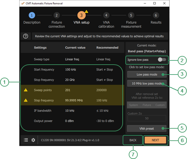
VNA setup
|
|
Analyzer Parameters Set the Analyzer parameters: •Start and stop frequencies, as well as the number of points. •IF bandwidth. •Output power level value. •Impedance conversion parameters (if necessary). |
|
|
Ignore low pass Checkbox Check this checkbox to ignore the recommended frequency grid. |
|
|
Low pass mode Button Click this button to set Fstart = Fstep, changing the start frequency and keeping the number of points unchanged. |
|
|
10 MHz low pass mode Button Click this button to set Fstart = Fstep = 10 MHz and the maximum stop frequency. |
|
|
VNA preset Button This button to set the default Analyzer parameters. |
|
|
NEXT Button Click this button to continue to the next step. |
|
|
BACK Button Click this button to return to the previous step. |


Instruction
1.Set the Analyzer parameters.
CAUTION |
The calculation of the fixture parameters is performed only with linear frequency sweep (uniform distribution of points in the frequency range). |
Click VNA preset button to set the default Analyzer parameters.
To quickly set the frequency grid corresponding to low pass mode, the plug-in has two buttons: Low pass mode and 10 MHz low pass mode:
The Low pass mode button – sets Fstart = Fstep, changing the start frequency and keeping the number of points unchanged.
The 10 MHz low pass mode button – sets Fstart = Fstep = 10 MHz and the maximum stop frequency.
CAUTION |
To ignore the recommended frequency grid check and not perform an impedance conversion, turn ON Ignore low pass toggle button. |
Manual input of Analyzer parameters:
•Enter values of frequency-dependent parameters: start and stop frequencies, as well as the number of points. The step is calculated automatically.
Warning |
Setting the number of points to more than 20,000 significantly decreases the speed of measurements and calculations. |
•Enter a value for the IF bandwidth. The choice of IF bandwidth is a compromise between the speed of measurement and the dynamics of S-parameter measurements. Wider bandwidth means higher speed, but less dynamics, i.e. less sensitivity of the Analyzer’s receivers. In most cases, the bandwidth is chosen in the range of 1 to 10 kHz.
•Enter the output power level value. Do not exceed 0 dBm. This can lead to compression of the Analyzer’s receivers and distortion of measurement results. At a low power level, the result may be too noisy. This will affect the quality of all correction methods implemented in the plug-in.
CAUTION |
Entering values other than the recommended ones results in an error message notification with an explanation of how to correct or change the parameter. The recommended values are indicated in the «Recommended» column. In most cases they are optional – their purpose is to facilitate the process of setting the Analyzer parameters. |
2.If necessary, select the impedance conversion parameters.
The impedance calculation and conversion functions are only available in low pass mode.
The plug-in is used to determine the parameters of the fixture and exclude its influence on the measurement result of the DUT, i.e. the plug-in is designed to shift the calibration plane of the Analyzer through the fixture directly to the device.
Depending on the fixture design, the characteristic impedance of its transmission lines may differ from the system impedance of the Analyzer. This means that without impedance conversion, the subsequently measured S-parameters of the device will be determined relative to the fixture impedance. If the impedance of the fixture and the Analyzer are significantly different, the S-parameters of the device will be offset.
The plug-in evaluates the impedance of the fixture’s transmission lines and allows to adjust its S-parameters so as to get the S-parameters of the device within the required impedance value.
The results of the impedance calculations along the length of the fixture can be viewed using Fixture measurement / Edit characterization.
Possible conversion options. The plug-in determines the fixture impedance and converts its calculated S-parameters relative to:
•System Analyzer impedance.
•The fixture impedance.
•Arbitrary impedance value.
After the conversion, the system impedance of the Analyzer is set to the selected value. In this case, the Analyzer, the loadable S-parameters of the fixture, and the S-parameters of the DUT will be linked to the same impedance value.