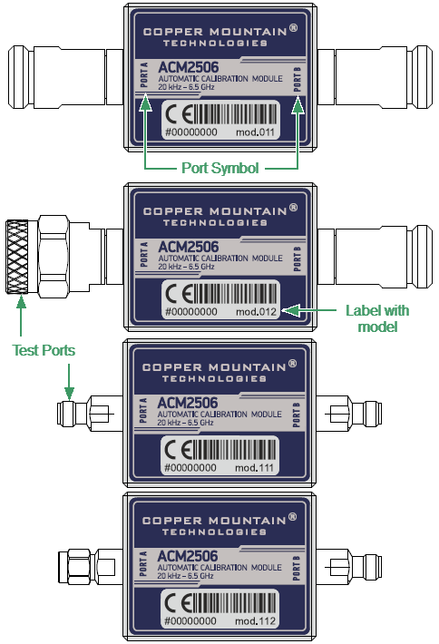
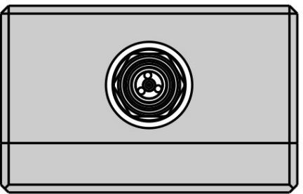
The front panels of the different models of ACM2506 are shown in the figure below.
Front panel ACM2506
Parts of the ACM2509
Test Port
The test ports are designed for connection to VNA being calibrated. The VNA connectors, the cross sections of which were calibrated, are referred to as its test ports.
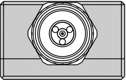
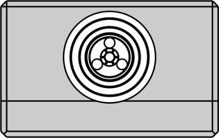
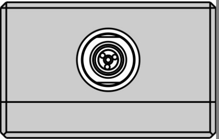
The Modules connectors are shown in figures below.
|
|
Type N, male |
Type N, female |
|
|
3.5 mm, male |
3.5 mm, female |
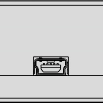
Mini USB Connector (on side panel)
|
The mini USB connector is located at the side panel of the Module and is intended for the Module connection to the controlling PC. The Module is powered using the USB cable. |
Hardware Configurations
Model |
Connector type |
|
|---|---|---|
Port A |
Port B |
|
ACM2506-011 |
type N, female |
type N, female |
ACM2506-012 |
type N, male |
type N, female |
ACM2506-111 |
3.5 mm, female |
3.5 mm, female |
ACM2506-112 |
3.5 mm, male |
3.5 mm, female |
Rev.: 25.1
