The front view of the Analyzers is represented in the figures below.
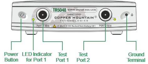
TR5048 Front Panel
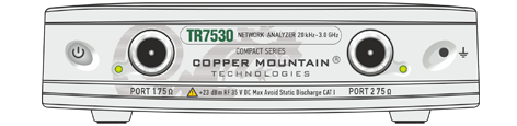
TR7530 Front Panel
Part of Front Panel
Power Button
|
Switches the Analyzer ON and OFF. The analyzer can be turned on/off at any time. The VNA loads its operating firmware from the PC each time upon powering up. The process will take approximately 10 seconds, after which the analyzer will be ready for operation. |

note |
The USB driver will be installed onto the PC when the analyzer is turned on for the first time. The driver installation procedure is described in Software Installation. Some PCs may require re-installation of the driver in case of change of the USB port. |
Test Ports
|
The type-N 50 Ω (type-N 75 Ω) test port 1 and test port 2 are intended for DUT connection. Test port 1 is used as a source of the stimulus signal and receiver of the incident and reflected wave signals. Test port 2 is used as a receiver of the response signal of the DUT. If the DUT is connected to test port 1 of the Analyzer, it is possible to measure the reflection parameter S11 of the DUT. If the DUT is connected to both test ports of the Analyzer, it is possible to measure S11 and S21 of the DUT. |

Caution |
Do not exceed the maximum allowed power of the input RF signal (or maximum DC voltage) indicated on the front panel. This may lead to damage of the Analyzer. |
Ground Terminal
|
Use the terminal for grounding. To avoid damage from electric discharge, connect the ground terminal on the body of the Analyzer to a reliable earth ground shared with the DUT in the test environment. |