The rear view of the Analyzers is represented in the figure below.
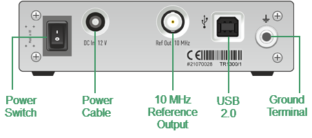
TR1300/1 Rear Panel
Parts of Rear Panel
Power Cable Receptacle
|
The power supply receptacle is intended for an external DC power supply voltage from 9 to 15 V; alternatively, the power supply can be powered by a battery, including a vehicle battery, through an appropriate vehicle power cable. The DC connection requires a 3.5x1.35 mm plug with positive center conductor. |

Power Switch
|
The analyzer can be turned on/off at any time. The VNA loads its operating firmware from the PC each time upon powering up. The process will take approximately 10 seconds, after which the analyzer will be ready for operation. The power switch serves as the disconnecting device (device that cuts off power supply) of the VNA. The power supply must be cut off to avoid such danger as electric shock, during prolonged non-use of the device. |

note |
The USB driver will be installed onto the PC when the analyzer is turned on for the first time. The driver installation procedure is described in Software Installation. Some PCs may require re-installation of the driver in case of change of the USB port. |
Reference Frequency Output Connector
|
External reference frequency is 10 MHz. Output reference signal level is 3 dBm ± 2 dB into 50 Ω impedance. Connector type is BNC female. |

USB 2.0 High Speed Port
|
The USB port is intended for connection to an external PC. |
Ground Terminal
|
To avoid electric shock, use this terminal for grounding. The Ground terminal allows to connect directly the body of the Analyzer to the test station ground in order to ensure electrical safety. |