The front view of the Analyzers is represented in the figure below.
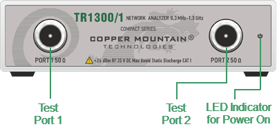
TR1300/1 Front Panel
Part of Front Panel
LED Indicator for Power On
|
LED Indicator for Power On is lit when the power switch located on the rear panel is turned on. |

Test Ports
|
The type-N 50 Ω test port 1 and test port 2 are intended for DUT connection. Test port 1 is used as a source of the stimulus signal and receiver of the incident and reflected wave signals. Test port 2 is used as a receiver of the response signal of the DUT. If the DUT is connected to test port 1 of the Analyzer, it is possible to measure the reflection parameter S11 of the DUT. If the DUT is connected to both test ports of the Analyzer, it is possible to measure S11 and S21 of the DUT. |

Caution |
Do not exceed the maximum allowed power of the input RF signal (or maximum DC voltage) indicated on the front panel. This may lead to damage of the Analyzer. |