note |
The availability of the TRL calibration depends on the Analyzer model (See corresponding datasheet). |
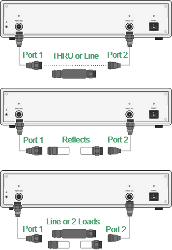
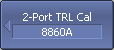
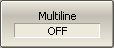
TRL (Thru-Reflect-Line) calibration is the most accurate calibration method described herein, as it uses airlines as calibration standards. The TRL calibration requires the use of the following calibration standards (See figure below):
•THRU or REFERENCE LINE
•REFLECT (SHORT or OPEN)
•second LINE or two MATCHes
TRL Calibration
TRL is a general name for a calibration family, which comprises such calibrations as LRL, TRM, or LRM — named depending on the calibration standards used.
If a zero-length THRU is used as the first standard, the method is called TRL calibration. If a non-zero length LINE is used as the first standard, the calibration method is called LRL (Line-Reflect-Line). To denote the first standard of the TRL and LRL calibration, assign TRL-Thru class, which includes THRU and LINEs. A LINE of TRL-Thru class is also called Reference Line.
An SHORT is usually used as a second standard in TRL calibration. To denote the second standard of the TRL calibration, assign TRL-Reflect class.
A second LINE is used as the third standard in TRL calibration. At low frequencies, two MATCHes are used instead of LINE, as they are an equivalent of a matched line of infinite length. In the latter case, the calibration method is called TRM (Thru-Reflect-Match) or LRM (Line-Reflect-Match) respectively. To denote the third standard of the TRL calibration, assign TRL-line/match class, which includes LINEs and MATCHes.
Frequency Range
TRL and LRL calibrations have a limited bandwidth, suitable for lower to upper frequency ratios up to 1:8. The band limits depend on the LINE length in TRL calibration or on the difference between the lengths of the two LINEs in LRL calibration.
In theory, TRM and LRM calibrations do not have limitations in frequency; however, their practical use at higher frequencies is limited by the quality of the MATCHes. It is recommended to use the TRM and LRM calibrations up to 1 GHz.
Impedance of LINEs and MATCHes
All the LINEs and MATCHes used for TRL calibration must have Z0 impedance values as precise as possible. TRL calibration transfers the impedance of standards into the calibrated system. Precise airlines with an accurate Z0 impedance of 50 Ω are used as LINEs in coaxial paths.
REFERENCE LINE
A zero-length THRU is used as the first standard in TRL calibration. In LRL calibration a LINE, which is called REFERENCE LINE, is used instead of a zero-length THRU. The shortest LINE is used as the REFERENCE LINE. Its length must to be known, so that the calibration plane positions could be calculated exactly. However, LRL calibration is also possible when the REFERENCE LINE length is not known. In this case, its length is assumed to be equal to zero, the calibration plane being in the middle of the LINE, and not at the ports’ edges.
TRL LINE
TRL LINE is an airline used in TRL calibration, or the second longest LINE used in LRL calibration. The length of TRL LINE should be known just approximately. The LINE length is used to determine the calibration bandwidth. Let ΔL be the difference between the two LINEs in LRL calibration. In TRL calibration this difference will be equal to the LINE length, as a zero-length THRU is used as a REFERENCE LINE. Then the phase difference between the TRL LINE and REFERENCE LINE or THRU should be no less than 20° at the lower frequency and no more than 160° at the upper frequency of the calibration.
,
where ,
— wave velocity in LINE (for airline it is с =2.9979·108 m/sec),
— REFERENCE LINE length,
— TRL LINE length.
So, the useful frequency range for TRL/LRL calibration is 1:8. Two or more TRL LINEs are used to extend the calibration frequency. For example, when using two TRL LINEs, the frequency range can be increased up to 1:64. Besides, TRL/LRL calibration does not work at low frequencies, as it would require a very long LINE.
TRL MATCH
Unlike TRL/LRL calibration, TRM/LRM calibration uses MATCHes, which are the equivalent to the infinitely long LINE, instead of a TRL LINE. Theoretically TRM/LRM calibration has no frequency limitations. However, the use of TRM/LRM calibration at higher frequencies is limited by the quality of the MATCHes. As a rule, the TRM/LRM calibration is used at lower frequencies, as it is good starting from zero frequency.
TRL REFLECT
There are no strict requirements to the TRL REFLECT standard. Only approximate parameters of the TRL REFLECT standard should be known. The REFLECT standard should have high reflection coefficient, close to 1. The phase of the standard must be known within ±90°. Normally, any SHORT meets this requirement. The next requirement is that the reflection coefficient must be the same for all the ports. If one standard is used for all the ports by turns, then this requirement is automatically fulfilled. If the ports have different genders or types of connectors, use special standards with the identical electrical specifications, which are available in pairs.
TRL Calibration Frequency Extension
To extend the frequency of TRL calibration a method of dividing into several non-overlapping bands is applied. For each frequency band a separate TRL LINE of different length is used. The phase difference between each TRL LINE and the REFERENCE LINE must be from 20° to 160°, as indicated above. A MATCH standard is used in the lowest frequency band.
The Analyzer software allows up to 8 LINES to be used for calibration frequency extension. To achieve this, there are two steps of handling the calibration kits:
•Defining frequency limits to calibration standards (See Calibration Standard Definition).
•Assigning classes to calibration standards, where up to 8 calibration standards can be assigned to one class (See Calibration Standard Class Assignment).
Perform the above mentioned dividing of the calibration band into sub-bands and assign a separate TRL LINE to each of them in the calibration kit editing menu before calibration.
Before starting calibration, perform the following settings: select active channel, set the parameters of the channel (frequency range, IF bandwidth, etc.), select the calibration kit.
|
To open TRL calibration submenu, use the following softkeys: Calibration > Calibrate > 2-Port TRL Cal |
|
To toggle between normal and Multiline TRL calibration, click Toggle softkey. |
|
Connect a TRL THRU (THRU or LINE) standard between the test ports. Perform measurement using the 1–2 Thru/Line softkey. Connect a TRL REFLECT standard to the test ports in any order. Perform measurement using Port 1 Reflect and the Port 2 Reflect softkey. Connect a TRL LINE/MATCH (LINE between the test ports and 2 LOADs to each port). Perform measurement using the Port 1-2 Line/Match softkey. The instrument status bar will indicate Calibration in progress... when the measurement is in progress. On completion of the measurement, a check mark will appear in the left part of the softkey. |

|
To complete the calibration procedure, click Apply. This will activate the process of calibration coefficient table calculation and saving it into the memory. The error correction function will also be automatically enabled. |

|
|
note |
System correction will turn automatically off when Apply softkey is pressed to perform TRL calibration (See System Correction Setting). |
|
To clear the measurement results of the standard, click Cancel. This softkey does not cancel the current calibration. To disable the current calibration, turn off the error correction function (See Error Correction Disabling). |

|
|
note |
The calibration status can be checked in channel status bar (See General error correction status table) or in trace status field (See Trace error correction status table). |