note |
The pulse measurement option is available for S5180B model. The license file is required (See Managing License). |
In the model S5180B Analyzer, there is a synchronizer, a pulse modulator, and a set of pulse generators that realize various pulse measurement modes.
Pulse Measurement Modes
The Analyzer supports three main modes for measuring the S-parameters of a pulsed DUT:
•Synchronous wideband mode (Point in Pulse) — measuring the frequency response of pulsed devices using wideband detection (see below). S-parameters are measured within one RF pulse at each frequency point. Modulation pulses are time synchronized with digital IF filter measurements
•Asynchronous narrowband mode — measuring the frequency response of pulsed devices using narrowband detection (see below). S-parameters are measured within a burst of RF pulses at each frequency point. The modulation pulses are not synchronized with the digital IF filter measurements. The measurement width of a digital IF filter is determined by the set filter bandwidth. The measurement width is selected larger than the pulse burst width. Each burst must contain more than 10 pulses
•Pulse profile mode — measurement of pulse parameters (amplitude envelope and pulse phase) in the time domain over the width of one RF pulse
note |
The following shortened forms of phrases will be used throughout the description: •Synchronous Wideband Measurement Mode (Point-in-pulse) is Point-in-pulse. •Asynchronous Narrowband Measurement mode is Asynchronous pulse. |
Wideband and Narrowband Detection
Detection is wideband when most of the spectrum of the RF pulse is within the passband of the IF filter (see figure below). This relationship between the characteristics of the filter and the signal spectrum occurs when the RF pulse width is greater than or equal to the measurement width of the digital IF filter and the measurement begins and ends within the width of each RF pulse. Since S-parameters are measured inside a RF pulse during wideband detection, in order to capture short RF pulses the Analyzer must have a wide IF filter bandwidth. The S5180B analyzer has a IF bandwidth of up to 300 kHz, which allows the capture of RF pulses from 4 μs.
Wideband detection is used in the “Point in Pulse” mode.
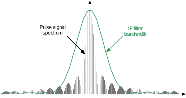
Wideband detection
Narrowband detection is used to measure short RF pulses that have a smaller width than can be measured by the wideband detection method.
Detection is narrowband when most of the RF pulse spectrum is outside the IF filter passband (See figure below). In this case, information is available only about the central component of the spectrum. This relationship between the characteristics of the filter and the signal spectrum occurs when the width of the measured RF pulses is significantly less than the width of one analyzer measurement.
The method uses the accumulation of bursts of identical RF pulses per width of one digital IF filter measurement. It is recommended to use more than ten RF pulses in a burst.
Narrowband detection is used in the “Asynchronous Narrow Band Mode” mode.
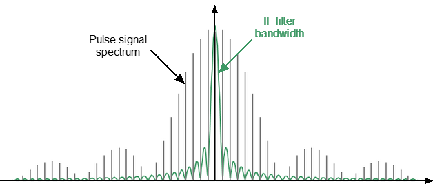
Narrowband detection
Comparison of Point-in-pulse and Asynchronous Pulse Mode
|
Point-in-pulse |
Asynchronous pulse |
|---|---|---|
Detection method |
Wideband detection |
Narrowband detection |
Advantages |
Preserves dynamic range when changing duty cycle |
Short pulse or high pulse repetition frequency capability |
Limitations |
Minimum pulse width limitation |
Dynamic range decreases with decreasing pulse duty cycle |
Pulse width |
|
|
Pulse repetition period (PRP) |
|
|
— frequency setting time when tuning to the next frequency. The typical and maximum values of frequency setting time are 16 μs and 50 μs respectively. |
||
Internal Generators
The Analyzer contains four internal generators named Pulse0 ... Pulse3. The purpose of the generators is as follows:
•Pulse0 is the modulator control.
•Pulse1, Pulse2 are output signals for controlling external devices.
•Pulse3 is an internal trigger.
Parameters of the Internal Pulse Generators
Parameter |
Value |
|---|---|
Time resolution |
100 ns |
Time range |
From 100 ns to 1 s |
Delay to external trigger |
From 100 to 300 ns |
Parameters of the internal modulator
Parameters |
Value |
|---|---|
The minimum pulse width |
200 ns |
Rise time |
50 ns |
Pulse Mode and Channels
Turning the pulse mode ON/OFF acts for all opened channels simultaneously. The following conditions are met automatically:
•All channels share the same internal generator settings and the same trigger settings.
•Channels using the point-in-pulse mode and channels using the pulse profile mode can coexist.
•Channels using the asynchronous pulse mode cannot coexist with channels using the point-in-pulse or pulse profile mode.
Trigger in Synchronous Pulse Modes
A special pulse trigger is used in synchronous modes "Point in pulse" and "Pulse profile". This trigger should not be confused with the standard mode trigger (See Trigger Settings). The pulse trigger has separate settings in the pulse mode menu (See Pulse Trigger Settings). The pulse trigger source can be internal (Pulse 3 generator) or external. If the source is internal, the user can set the trigger repetition period, and, accordingly, RF pulses repetition period in the software interface.
Purpose of BNC Connectors (Rear Panel of the Analyzer)
Connector |
"Point in Pulse" and "Pulse Profile" modes |
Asynchronous pulse mode |
||
|---|---|---|---|---|
Internal pulse trigger |
External pulse trigger |
Internal modulation source |
External modulation source |
|
Mod Pulse In/Out |
Modulation pulses output (Pulse0 generator) |
Modulation pulses output (Pulse0 generator) |
Modulation pulses input (external generator) |
|
Pulse 1 Out |
Pulse1 generator output (optional) |
"Ready for pulse" signal output or Pulse1 generator output |
Output of the trigger in the standard mode (See Trigger Output) |
|
Pulse 2 In/Out |
Pulse2 generator output (optional) |
Input of an external pulse trigger |
Input of the trigger in the standard mode (See External Trigger Settings) |
|