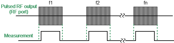
The “Point in Pulse” mode is designed to measure the frequency characteristics of a pulsed DUT. In this mode, the same parameters are measured as in the standard measurement mode of the Analyzer (S-parameters, wave magnitudes). The mode is so called because the measurement "point" is located inside the RF pulse. The term "dot" refers to the measurement width of the digital IF filter of the Analyzer. RF pulse data is sampled at this time. To perform a frequency sweep, the Analyzer generates a series of RF pulses, in which each pulse is generated at its own frequency fn, from the frequency range of the sweep. Thus, the S-parameter measurement at one frequency point is completed within each RF pulse (see figure below). The number of RF pulses in the burst will be equal to the set number of sweep points.
Point in Pulse mode
Wideband detection is used in the "Point in Pulse" mode (see Wideband and Narrowband detection). The advantage of the "Point in Pulse" method is the preservation of the dynamic range of measurements regardless of pulse duty cycle. A limitation of the method is that the minimum possible pulse width cannot be less than the measurement width of the widest IF filter.
The minimum pulse width for the Analyzer is calculated as:
Point-in-pulse with an Internal Trigger
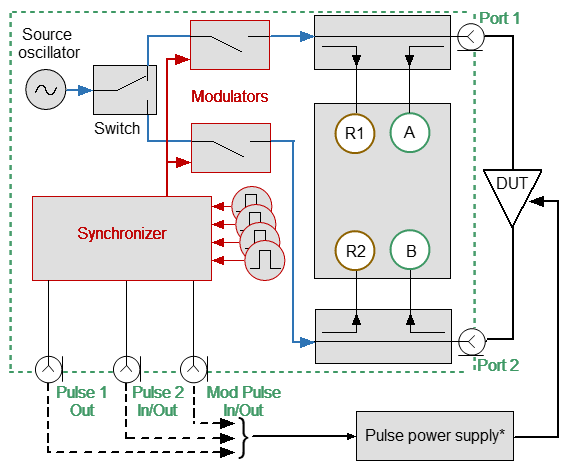
In this mode, the internal Pulse3 generator is the source for the pulse trigger (see figure below). The trigger pulse repetition period is set via the software interface. All delays are referenced to the trigger (see figure Timing diagram of the synchronous pulse mode).
•The internal generator Pulse0 creates pulses for modulators with a user-specified width and delay.
•The measurement is performed with a specified width and delay (the width is selected from a series of discrete values corresponding to a set of IF filters). It is necessary to set the measurement width lower than the modulation pulse width. It is necessary to set the delay ratio of the modulation pulse and the measurement pulse so that the measurement is located inside the RF pulse.
•The internal generators Pulse1 and Pulse 2 generate pulses with a user-specified width and delay, which can be used to control external devices (including modulation of supply voltages). The pulse width and delay of these generators are set via the software interface.
* Optional |
Pulse-in-pulse with internal trigger
In the internal trigger mode, the BNC connectors are used as follows:
•Mod Pulse In/Out is the internal modulation pulse output.
•Pulse 1 Out is the Pulse1 output (optional).
•Pulse 2 In/Out is the Pulse2 output (optional).
Point-in-pulse with an External Trigger
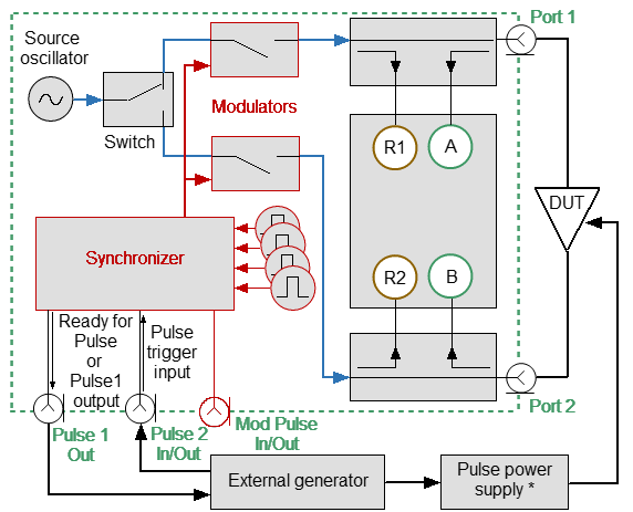
In this mode, the external generator is the source of the pulse trigger. External generator pulses are supplied to the Pulse 2 In/Out connector (see figure below). The external generator setting determines the pulse repetition period. All delays are referenced to the trigger (see figure Timing diagram of the synchronous pulse mode).
•The internal generator Pulse0 creates pulses for modulators with a user-specified width and delay.
•The measurement is performed with a specified width and delay (the width is selected from a series of discrete values corresponding to a set of IF filters). It is necessary to set the measurement width lower than the modulation pulse width. It is necessary to set the delay ratio of the modulation pulse and the measurement pulse so that the measurement is located inside the RF pulse.
•The internal generator Pulse1 generates pulses with a user-specified width and delay that can be used to control external devices (including modulation of supply voltages). The pulse width and delay of this generator are set via a software interface.
•If the repetition rate of the external trigger is too high, a trigger may be lost. To avoid this situation, the "Ready for Pulse" signal can be enabled for output to a Pulse1 Out BNC connector.
note |
In external trigger mode, the Pulse 1 Out connector can be used as a Pulse1 generator output or as a "Ready for Pulse" signal output. |
* Optional |
External Trigger
In the external trigger mode, the BNC connectors are used as follows:
•Mod Pulse In/Out is the internal pulse modulation output.
•Pulse 1 Out is either the Ready for Pulse or Pulse1 output.
•Pulse 2 In/Out is the external trigger input.
Step-by-step Setup of the Point in Pulse Mode
•Configure the channel (sweep range, power, sweep type, and number of points) according to the requirements of the DUT.
•Set the pulse trigger source (internal or external). All other signals are referenced to this trigger (see figure below). The internal trigger source is the internal Pulse3 generator. The external trigger source is an external generator connected to the Pulse 2 In/Out input.
•Set the pulse repetition period in the software when using an internal trigger.
note |
The Analyzer requires time to set the frequency between pulses. Typical setting times are given in the Analyzer datasheet. Setting time may increase further at analyzer range switching points. The pulse trigger is ignored if it arrives before the analyzer frequency setting is complete, and the measurement will be started by the next trigger. This means that more pulses may be required to complete the sweep, and the pulse repetition period may vary upward. Use a "Ready for Pulse" signal to avoid loss of trigger pulses when using an external trigger. To do this, connect this signal to the Pulse 1 Out connector. |
•Select the width and delay of the measurement so that the measurement is placed within the width of the RF pulse. The measurement width is determined by the set IF filter bandwidth, so it is selected from a discrete set of values. Please note that the measurement width should not exceed the modulation pulse width. It is recommended to set the measurement delay so that the measurement is centered in the center of the RF pulse.
Timing Diagram of the Point in Pulse Mode
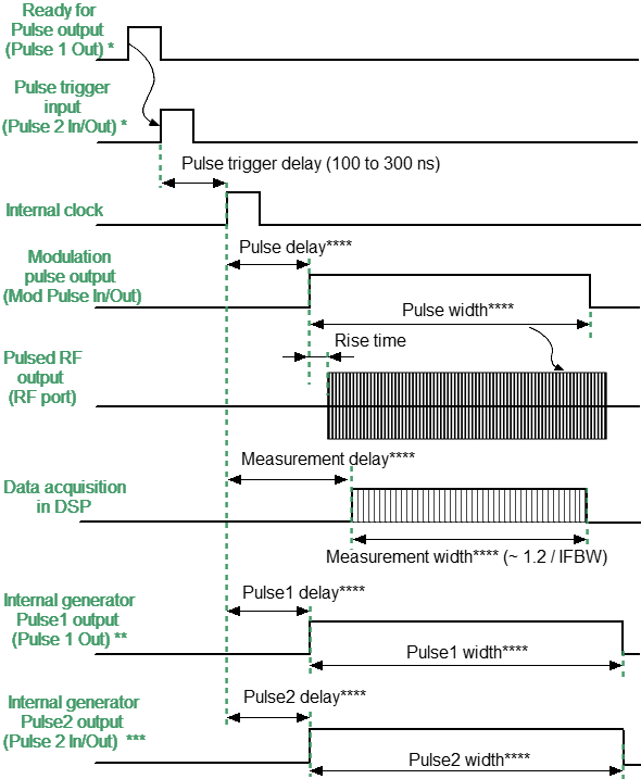
* Optional |
** Available when Ready for Pulse is not used |
*** Available when Internal Trigger is not used |
**** User setting |
Timing diagram of the synchronous pulse mode
note |
For setting the mode in the program interface, see Pulse Measurement Procedure. |