The “Asynchronous pulse” mode is designed to measure the frequency characteristics of a pulsed DUT. In this mode, the same parameters are measured as in the standard measurement mode of the Analyzer (S-parameters, wave magnitudes). This mode is used to measure short RF pulses whose width is smaller than can be measured using the "Point in Pulse" method. In asynchronous pulse mode, the Analyzer performs standard measurements, but instead of a continuous RF signal, a modulated signal is applied to the DUT input. The Analyzer performs a frequency sweep and measures S-parameters at each frequency point asynchronously with RF pulses. In this case, it is critical that many pulses (more than 10) are measured within the width of one IF filter measurement for reliable signal detection and measurement.
Asynchronous pulse
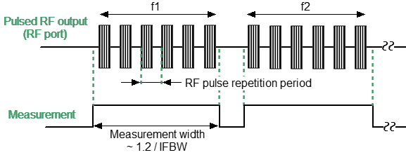
The IF filter bandwidth determines the measurement width and is selected based on the RF pulse repetition period. It is recommended that the measurement width is greater than 10 RF pulse repetition periods. The relationship between measurement width and IF bandwidth is determined by the formula: Measurement width = 1.2/IFBW.
The source of modulation pulses is an internal or external generator. When using an external generator, its signal goes directly to the modulators. When using an internal generator, it is necessary to set the modulation pulse width and repetition period for it in the software.
The asynchronous pulse method uses narrowband detection (See Wideband and Narrowband detection). The advantage of the asynchronous method is the ability to use much higher pulse repetition rates and much shorter pulse widths compared to the "Point in Pulse" method. The dynamic range loss depends on the pulse duty cycle Q and is expressed as 20log(Q).
note |
In this mode, the absolute value of the wave amplitudes (receivers) does not correspond to the real value of the power of the incident or transmitted wave, in contrast to the “Point in Pulse” mode. The power value will be lower than the actual value in inverse proportion to the duty cycle of the modulation pulses. |
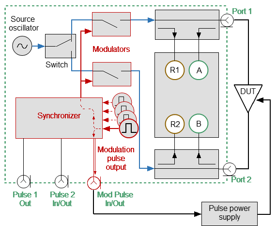
Asynchronous Pulse Mode with an Internal Source utilizes the internal generator Pulse0 as a pulse source for modulators with a user-specified period and width (see figure below).
* Optional |
Asynchronous pulse mode with internal source
The BNC connectors are used as follows:
•Mod Pulse In/Out is the modulation Pulse0 output.
•Pulse 1 Out function is the same as in standard measurement mode (see Trigger Output).
•Pulse 2 In/Out function is the same as in standard measurement mode (see External Trigger Settings).
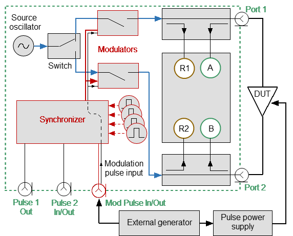
Asynchronous Pulse Mode with an External Source utilizes an external generator which is used as a pulse source for modulation (see figure below).
* Optional |
Asynchronous pulse mode with external source
The BNC connectors are used as follows:
•Mod Pulse In/Out is the external pulse generator input.
•Pulse 1 Out functions the same as in standard measurement mode (see Trigger Output).
•Pulse 2 In/Out functions the same as in standard measurement mode (see External Trigger Settings).
Step-by-step Setup of the Asynchronous pulse Mode
•Configure the channel (sweep range, power, sweep type, and number of points) according to the requirements of the DUT.
•Set the source of modulating pulses (internal or external). The internal source of modulating pulses is the internal Pulse0 generator. The external trigger source is an external generator connected to the Mod Pulse In/Out input.
•Set the modulation pulses to repetition period and pulse width values when using the internal source.
•Select the measurement width based on the pulse repetition period and the requirement for the minimum number of pulses in the burst (at least 10). The measurement width is determined by the IF filter bandwidth, so it is selected from a discrete set of values. Select the closest measurement width value, not less than the product of the pulse repetition period and the number of pulses in the burst.
note |
For setting the mode in the program interface, see Pulse Measurement Procedure. |