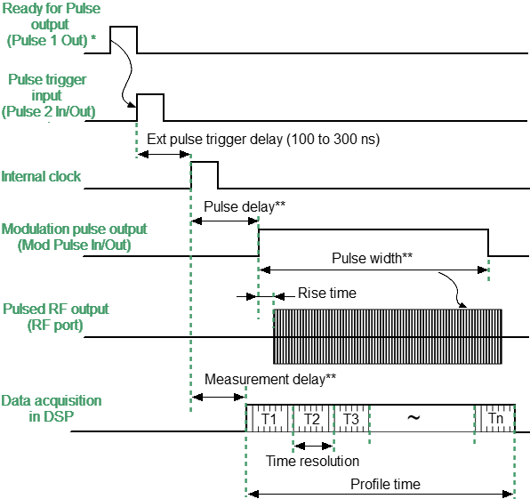
In Pulse Profile mode, the pulse envelope is measured in the time domain. The pulse envelope measurement includes amplitude and phase (S-parameters) at each sweep point. All points on the pulse profile trace are measured over the width of one RF pulse. The number of measurement points is determined by the ratio of the user-specified profile width and the profile time resolution. The time resolution of the profile is equal to half the measurement width of the selected IF filter, the minimum value is:
The pulse profiling is performed at a single CW frequency. CW frequency is set to the center of the sweep band. Absolute measurement trace is used to observe the pulse amplitude envelope. In both the "Pulse Profile" and "Point-in-Pulse" modes, the block diagram, internal generator settings, and trigger settings are the same.
Step-by-step Setup of the Pulse Profile Mode
•Configure the channel (CW frequency, power) according to the requirements of the DUT.
•Select the absolute measurement trace to measure pulse amplitude, and select the S21 trace to measure pulse phase.
•Set the pulse trigger source (internal or external). All other signals are referenced to this trigger (see figure below). The internal trigger source is the internal Pulse3 generator. The external trigger source is an external generator connected to the Pulse 2 In/Out input.
•Set the pulse repetition period in the software when using an internal trigger.
note |
The Analyzer needs time to initialize a new sweep between pulses (retrace time). The trigger will be ignored if it arrives before the retrace time is completed. Thus, the pulse repetition period will be equal to the greater of two values: the pulse trigger period and the analyzer retrace time. |
•Use a "Ready for Pulse" signal to avoid loss of trigger pulses when using an external trigger. To do this, connect this signal to the Pulse 1 Out connector.
•Set the width and delay of the modulation pulse. The pulse profile trace can be shifted to the right on the screen using a delay.
•Set the pulse profile width and measurement delay. It is recommended to choose a profile width equal to the width of one pulse, with such a margin that the pulse is placed on most of the screen. The pulse envelope can be displayed in whole or in part by changing the profile width. The pulse profile trace can be shifted to the left on the screen using a measurement delay.
•The Analyzer automatically selects the point time resolution and number of sweep points when the pulse profile length is set. The minimum possible time resolution is always selected. Number of points N = profile width / resolution. The time resolution increases if the calculated number of points exceeds 2001.
The measurement results for the intervals T1 ... Tn are presented in the time domain.

* Optional |
** User setting |
Timing diagram of the Pulse Profile mode
note |
For setting the mode in the program interface, see Pulse Measurement Procedure. |