note |
The pulse measurement option is available for S5243 model. The license file is required (see Managing License). |
In the model S5243 analyzer, there are pulse generators, a modulator, and four synchronization connectors. One of them is an input, and three are outputs of logical pulses for external devices.
Basic and Advanced Pulse Modes
Various pulse measurement modes are implemented in the Analyzer using a built-in pulse modulator, a set of programmable pulse generators, and a pulse measurement unit. These blocks of the Analyzer are based on FPGA. The FPGA blocks can be connected to each other using a variety of schemes. Pulse generators possess the flexibility to be programmed to generate diverse types of pulses with varying widths and delays. The Analyzer supports several basic pulse measurement modes, in which the analyzer software performs all settings for the internal blocks of the FPGA. The user only selects the measurement mode and sets the numerical measurement parameters, for example, pulse width, pulse repetition period, etc. In the advanced mode, the user has access to a larger selection of settings for generators and FPGA block structures, which requires the user to know the logic of the FPGA operation. The remainder of this document describes only the basic pulse measurement modes. The advanced pulse measurement mode is described in a separate document.
Pulse Measurement Modes
The Analyzer supports five main modes for measuring the S-parameters of a pulsed device:
•Point in Pulse — measuring the frequency response of pulsed devices using wideband detection (see below). S-parameters are measured within one RF pulse at each frequency point. Modulation pulses are time synchronized with digital IF filter measurements
•Narrowband — measuring the frequency response of pulsed devices using narrowband detection (see below). S-parameters are measured within a burst of RF pulses at each frequency point
•Pulse Profile — measurement of pulse parameters (amplitude envelope and pulse phase) in the time domain over the width of one RF pulse
•Pulse Profile (High Resolution) — pulse profile measurement with higher time resolution, using a series of pulses instead of one
•Pulse to Pulse — tracking the drift of DUT parameters over the width of a burst of pulses with one carrier frequency
Wideband and Narrowband Detection
Detection is wideband when most of the spectrum of the RF pulse is within the passband of the IF filter (see figure below). This relationship between the characteristics of the filter and the signal spectrum occurs when the RF pulse width is greater than or equal to the measurement width of the digital IF filter and the measurement begins and ends within the width of each RF pulse.
Since S-parameters are measured inside an RF pulse during wideband detection, in order to capture short RF pulses the Analyzer must have a wide IF filter bandwidth. The S5243 analyzer has a IF bandwidth of up to 10 MHz, which allows the capture of RF pulses from 100 ns.
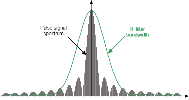
Wideband detection
Narrowband detection is used to measure short RF pulses that have a smaller width than can be measured by the wideband detection method.
Detection is narrowband when most of the RF pulse spectrum is outside the IF filter passband (see figure below). In this case, information is available only about the central component of the spectrum. This relationship between the characteristics of the filter and the signal spectrum occurs when the width of the measured RF pulses is significantly less than the width of one analyzer measurement.
The method uses the accumulation of bursts of identical RF pulses per width of one digital IF filter measurement. It is recommended to use more than ten RF pulses in a burst.
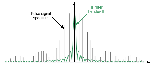
Narrowband detection
Comparison of Wideband and Narrowband Detection
|
Wideband detection |
Narrowband detection |
|---|---|---|
Advantages |
Preserves dynamic range when changing duty cycle |
Short pulse capability |
Limitations |
Minimum pulse width limitation (determined by the maximum IF filter bandwidth) |
Dynamic range decreases with decreasing pulse duty cycle |
Pulse width |
more than 100 nc |
more than 20 nc |
Supported measurement modes |
Software Gating
The software gating method is used to improve the signal-to-noise ratio in narrowband detection. This method excludes from the digitized measurement results the influence of transient processes when turning the modulator on/off and any noise during those periods of time when modulation is turned off. The gating pulse is supplied to the software data reset unit from one of the internal pulse generators. The data from the ADC is fed to the digital IF filter when the gate signal is “1”. The digital IF filter input is set to "0" when the gate signal is "0".
Software gating is used in Narrowband mode and Pulse Profile (High Resolution) mode.
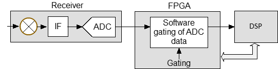
Block diagram of the software gating method hardware
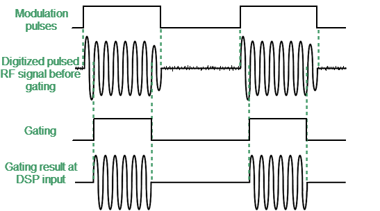
Timing diagram of software gating mode
Filters and Window Functions
When the user selects a measurement width, the software sets the appropriate IF filter bandwidth from the available range. The window function type corresponds to the set IF filter bandwidth. The type of window function affects the width of the dimension. The following IF filters and windowing functions are supported by the Analyzer.
Digital filters supported by the Analyzer
IF filter band |
Window function type |
Calculation of measurement width |
|---|---|---|
1 Hz to 300 kHz |
Tukey |
|
500 kHz to 2 MHz |
Hanning |
|
3 MHz, 5 MHz, 7.5 MHz, 10 MHz |
Rectangular window |
|
Purpose of Pulse Generators
Seven identical pulse generators IG1...IG7 are implemented in FPGA. In the basic mode, the purpose of the pulse generators is fixed and cannot be changed by the user. Generator parameters such as pulse repetition period, pulse width, and pulse delay can be changed.
Pulse generators PG1...PG3, and PG7 provide internal synchronization of pulse measurements.Signals from pulse generators PG4...PG6 can be output to Trig 4...Trig 6 connectors on the rear panel of the Analyzer. These signals are used to control external devices.
Pulse Generator |
Purpose |
Custom Setting |
|---|---|---|
PG1 |
Internal pulse trigger source. Sets the pulse repetition period. Not used when selecting external trigger |
not available |
PG2 |
Control of “normal” and “fast” modulators |
|
PG3 |
Starting measurements |
|
PG4 |
Control of external devices. Signal transmission to the "Trig 4" connector on the rear panel of the Analyzer |
delay, width, polarity |
PG5 |
Control of external devices. Signal transmission to the "Trig 5" connector on the rear panel of the Analyzer. |
|
PG6 |
Control of external devices. Signal transmission to the "Trig 6" connector on the rear panel of the Analyzer. |
|
PG7 |
Software gating |
not available |
Pulse Trigger Source Selection
The pulse trigger determines the pulse repetition period and the time point from which the start delays of the remaining pulse generators are counted. An internal or external pulse generator can be selected as a trigger source.
It is possible to set the pulse repetition period if the trigger source is the internal PG1 generator.
If an external trigger source is selected, the pulse repetition period is determined by the settings of the external generator. The external generator signal must be connected to the Trig 3 connector on the rear panel of the Analyzer.
note |
The External Trigger and Output Trigger connectors used in the standard trigger mode (see Trigger Settings) are not used in the pulse mode. |
The formation and measurement of each pulse within the sweep are triggered by pulse trigger. The Analyzer requires time to set the frequency between pulses. Typical setting times are given in the Analyzer data sheet. Setting time may increase further at analyzer range switching points. The pulse trigger is ignored if it arrives before the analyzer frequency setting is complete, and the measurement will be started by the next trigger. This means that more pulses may be required to complete the sweep, and the pulse repetition period may vary upward.
Pulse Modulator Type
There are two types of pulse modulators available: “normal” and “fast”. The “normal” type provides high attenuation between pulses, but has a minimum pulse width limit. The “fast” type can generate very short pulse widths, but does not provide high attenuation in the interval between pulses. The exact parameters of the modulators are given in the datasheet of the Analyzer.
Use the "fast" type of modulator for pulses less than 1 µs. Select the modulator type based on the required modulation depth for longer pulses. Select the "normal" modulator type if greater modulation depth is required. The actual pulse width may be slightly less than the specified width due to the limited speed of a “normal” modulator, which is noticeable for pulses less than 10 µs. In this case, check the actual pulse width by observing the incident wave power in the Pulse Profile (High resolution) mode on the appropriate receiver R and changing the pulse width.
Measurement Delay
It is important that the measurement is performed within an RF pulse for modes such as Point in Pulse and Pulse to Pulse. However, the RF pulse has a delay relative to the pulse trigger, caused by the delay in turning on the modulator and the delay in signal propagation in the DUT connection circuits. In addition, there is a delay of the digital signal at the ADC output relative to the input analog signal. The above delays are summed up, shifting the moment of measurement towards the delay relative to the RF pulse. To compensate for this delay, it is necessary to set a measurement delay in the program that must be no less than the aggregate delay described above. The start of the measurement will coincide with the start of the RF pulse if the measurement delay is equal to the aggregate delay. The measurement will shift towards the trailing edge of the RF pulse as the measurement delay increases. Therefore, it is important to ensure that the delay does not increase so much that the trailing edge of the measurement moves beyond the trailing edge of the RF pulse. The typical aggregate delay of the ADC and fast modulator is about 400 ns, its value is set by default in the software as the measurement delay. The typical aggregate delay of an ADC and a normal modulator is about 1200 ns. It is possible to experimentally determine the aggregate delay by measuring the signal path without a DUT in the “Pulse Profile (High Resolution)” mode, as shown in the figure below.
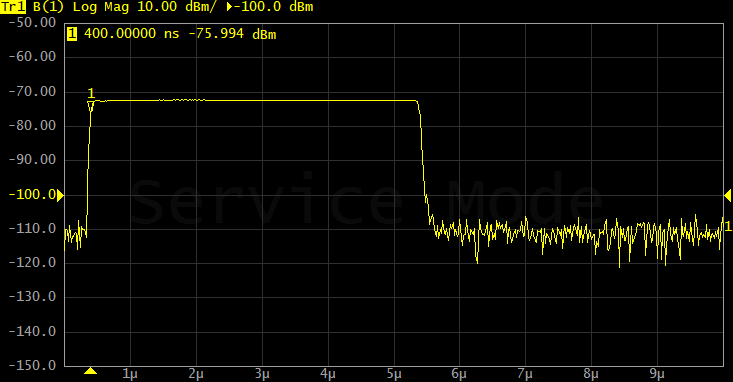
Determination of the aggregate delay of the modulator and the delay of the fixture connecting the DUT
Timing Diagram
A timing diagram can be displayed for clarity when setting up pulse measurement modes. The following information is displayed on it:
•moment of arrival of the pulse trigger, pulse trigger source (internal or external), repetition period
•modulator pulse
•measurement width
•number of pulses in a burst (narrowband mode)
•pulse generator signals, if used
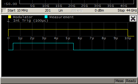
Example timing diagram