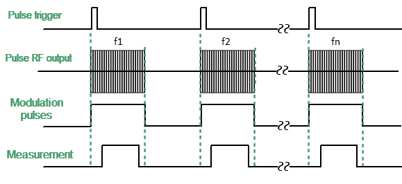
The “Point in Pulse” mode is designed to measure the frequency characteristics of a pulsed DUT. In this mode, the same parameters are measured as in the standard measurement mode of the Analyzer (S-parameters, wave magnitudes). The mode is so called because the measurement "point" is located inside the RF pulse. The term "dot" refers to the measurement width of the digital IF filter of the Analyzer. RF pulse data is sampled at this time. To perform a frequency sweep, the Analyzer generates a series of RF pulses, in which each pulse is generated at its own frequency fn, from the frequency range of the sweep. Thus, the S-parameter measurement at one frequency point is completed within each RF pulse (See figure below). The number of RF pulses in the burst will be equal to the set number of sweep points. The “Point in Pulse” mode allows you to use a power sweep instead of a frequency sweep. In this case, each RF pulse is generated with its own power Pn at a CW frequency.
Point in Pulse mode
Wideband detection is used in the "Point in Pulse" mode (see Wideband and Narrowband detection). The advantage of the "Point in Pulse" method is the preservation of the dynamic range of measurements regardless of pulse duty cycle.
A limitation of the method is that the minimum possible pulse width cannot be less than the measurement width of the widest IF filter. The minimum measurement width is 80 ns. The recommended minimum RF pulse width is 100 ns, allowing for a margin for synchronization error.
Step-by-step Setup of the Point in Pulse Mode
•Configure the channel (sweep range, power, sweep type, and number of points) according to the requirements of the DUT.
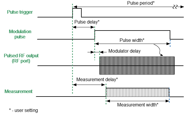
•Set the pulse trigger source (internal / external). All other signals are referenced to this trigger (see figure below). The internal trigger source is the internal PG1 generator. The external trigger source is an external generator connected to the Trig 3 input.
•Set the pulse repetition period in the software when using an internal trigger.
note |
The Analyzer requires time to set the frequency between pulses. Typical setting times are given in the Analyzer datasheet. Setting time may increase further at analyzer range switching points. The pulse trigger is ignored if it arrives before the analyzer frequency setting is complete, and the measurement will be started by the next trigger. This means that more pulses may be required to complete the sweep, and the pulse repetition period may vary upward. |
•Select the modulator type (normal / fast) and set the modulation pulse width and delay (usually 0). The signal from the internal generator PG2 controls the modulator.
•Select the width and delay of the measurement so that the measurement is placed within the width of the RF pulse. The measurement width is determined by the set IF filter bandwidth, so it is selected from a discrete set of values. Please note that the measurement width should not exceed the modulation pulse width. It is recommended to set the measurement delay so that the beginning of the measurement coincides with the beginning of the RF pulse (See Measurement delay). Increase the delay based on the ratio of pulse width to measurement width to more accurately center the measurement on the RF pulse. The internal generator PG3 provides a measurement delay.
Settings for the Point in Pulse mode
note |
For setting the mode in the program interface, see Pulse Measurement Procedure. |