The “Narrowband” mode is designed to measure the frequency characteristics of a pulsed DUT. In this mode, the same parameters are measured as in the standard measurement mode of the Analyzer (S-parameters, wave magnitudes). This mode is used to measure short RF pulses whose width is smaller than can be measured using the "Point in Pulse" method. Unlike the “Point in Pulse” mode, a burst of RF pulses with one carrier frequency is used to measure at one frequency sweep point. In this case, the width of one measurement by a digital IF filter must be no less than the width of a burst of radio pulses. The full frequency sweep will be formed from N packets of RF pulses. Each of the bursts has a frequency fn from the frequency sweep range (see figure below). Instead of a frequency sweep, a power sweep can be used.
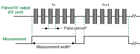
Sweep in Narrowband mode
The figure below shows measurements at a single sweep point in the Narrowband mode in more details. The Analyzer generates a burst of RF pulses with one carrier frequency. All pulses of the burst are averaged during measurement. At the same time, a software gating method is used to improve the signal-to-noise ratio. The method resets the ADC data during periods when modulation is disabled. The number of pulses in a burst is determined by the ratio of the selected measurement width and the pulse repetition period. The measurement duration can be selected by the user from an available range of IF filters. The measurement width can be selected by the user from an available discrete range of IF filters. It is recommended that the number of pulses in a packet should be at least 10.
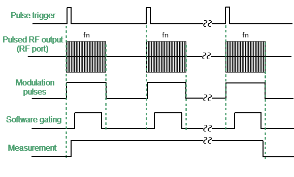
Measurement at one sweep point in Narrowband mode
The advantage of the Narrowband method is the ability to use much higher pulse repetition rates and much shorter pulse widths compared to the "Point in Pulse" method. The Analyzer supports pulse widths ranging from 20 ns. The limitation of this mode is that the dynamic range of measurements decreases with increasing pulse duty cycles.
note |
In this mode, the absolute value of the wave amplitudes (receivers) does not correspond to the real value of the power of the incident or transmitted wave, in contrast to the “Point in Pulse” mode. The power value will be lower than the actual value in inverse proportion to the duty cycle of the modulation pulses (or the duty cycle of software gating pulses, if software gating is enabled). |
Step-by-step Setup of the Narrowband Mode
•Configure the channel (sweep range, power, sweep type, and number of points) according to the requirements of the DUT.
•Set the pulse trigger source (internal / external). All other signals are referenced to this trigger (See figure below). The internal trigger source is the internal PG1 generator. The external trigger source is an external generator connected to the Trig 3 input.
•Set the modulation pulses to repetition period and pulse width values when using the internal source.
note |
The repetition period of trigger pulses within one burst of pulses in ranging from 20 ns. The Analyzer requires time to set the frequency between pulse bursts. Typical setting times are given in the Analyzer datasheet. Setting time may increase further at analyzer range switching points. The pulse trigger is ignored if it arrives before the analyzer frequency setting is complete, and the measurement will be started by the next trigger. This means that more pulses may be required to complete the sweep, and the pulse repetition period may vary upward. |
•Select the measurement width based on the pulse repetition period and the requirement for the minimum number of pulses in the burst (at least 10). The measurement width is determined by the IF filter bandwidth, so it is selected from a discrete set of values. Select the closest measurement width value, not less than the product of the pulse repetition period and the number of pulses in the burst.
note |
The number of pulses in a burst is set by setting the pulse repetition period and measurement width. The actual number of pulses in a burst is displayed numerically on the timing diagram. |
•Set the measurement delay so that the beginning of the measurement coincides with the beginning of the RF pulse (see Measurement delay). This delay occurs before the first pulse of the burst, so its impact is much less than in the “Point in Pulse” mode. The internal generator PG3 provides a measurement delay.
•Turn on software gating of the ADC to improve the signal-to-noise ratio. The internal generator PG7 provides pulses of software gating.
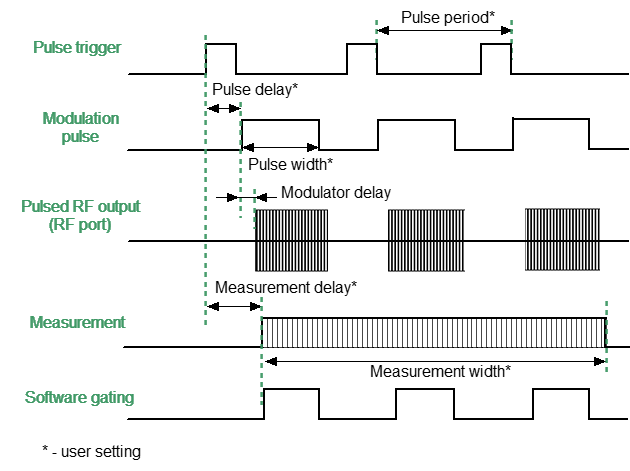
Narrowband mode settings
note |
For setting the mode in the program interface, see Pulse Measurement Procedure. |