In the "Pulse Profile" mode, the temporal characteristics of the pulse are measured, such as the width of the edges and surges on the edges, as well as the decay of the top of the pulse. This mode measures the time dependence of S-parameters and wave quantities (receivers) along the width of a single pulse. The pulse profiling is performed at a single CW frequency and at a fixed stimulus power. CW frequency is set to the center of the sweep band. The trace of the transmitted wave receiver should be used to measure the pulse envelope.
All points on the pulse profile trace are measured over the width of one RF pulse. The number of measurement points is determined by the ratio of the specified profile width and the profile time resolution. It is recommended to select a profile width equal to the width of one pulse, with such a margin that the pulse is placed over most of the screen. The time resolution is selected from a range corresponding to a discrete set of IF filters. The Analyzer's minimum time resolution of 100 ns corresponds to a 10 MHz IF filter.
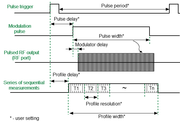
The measurement results for the intervals T1...Tn is presented on the time domain pulse profile trace.
Pulse Profile mode settings
Step-by-step Setup of the Pulse Profile Mode
•Configure the channel (CW frequency, power) according to the requirements of the DUT.
•Select the absolute measurement trace to measure pulse amplitude, and select the S21 trace to measure pulse phase.
•Set the pulse trigger source (internal / external). All other signals are referenced to this trigger (see figure below). The internal trigger source is the internal PG1 generator. The external trigger source is an external generator connected to the Trig 3 input.
•Set the pulse repetition period in the software when using an internal trigger.
note |
The Analyzer needs time to initialize a new sweep between pulses (retrace time). The trigger will be ignored if it arrives before the retrace time is completed. Thus, the pulse repetition period will be equal to the greater of two values: the pulse trigger period and the analyzer retrace time. |
•Select the modulator type (normal / fast) and set the modulation pulse width and delay. The pulse profile trace can be moved to the right on the screen using a modulation pulse delay. The signal from the internal generator PG2 controls the modulator.
•Set the pulse profile width and measurement delay. The pulse can be displayed on the screen in whole or in part by changing the profile width. The pulse profile trace can be moved left on the screen using the pulse profile delay. Internal generators PG3 and PG7 produce pulses for the pulse profile mode.
note |
For setting the mode in the program interface, see Pulse Measurement Procedure. |