The Analyzer ensures a steady power level at test port 1 with the specified accuracy. The power level is defined between the instrument’s minimum and maximum output power level.
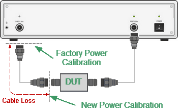
A DUT is connected to the Analyzer by cables (see figure below), which have some losses. The power calibration allows maintaining a more accurate power level at a DUT input, adjusted to the use of the cables.
Power Calibration
The power calibration is performed by an external power meter connected to the cables’ end which will be later connected to the DUT input. After the power calibration is complete, power correction automatically turns on. Later it is possible to disable or enable again the power correction function.

Power Calibration with External Power Meter
The power calibration is performed for each channel individually.
note |
The power correction status is indicated in the channel status bar (See Channel Status Bar). |
Power Calibration Procedure
Perform connection and setting of an external power meter as described in Power Meter Setting. Connect the sensor to test port 1 of the Analyzer and perform calibration as described below.
|
To open power calibration submenu, use the following softkeys: Calibration > Calibrate > Power Calibration |
|
To zero power meter, use the following softkeys: Calibration > Power Calibration > Zeroing |

note |
The power meter sensor can be connected to the port, as during zero setting the output signal of the port is turned OFF. |
|
To execute power calibration, use the following softkeys: Calibration > Power Calibration > Calibrate |

|
|
note |
After the power calibration is complete, power correction automatically turns ON. |
Power Correction Setting
|
To enable/disable power correction, use the following softkeys: Calibration > Power Calibration > Correction [ON | OFF] |
|
|