The limit test is a function of automatic pass/fail judgment for the trace of the measurement result. The judgment is based on the comparison of the trace to the limit line set by the user.
The limit line can consist of one or several segments (See figure below). Each segment checks the measured value for failure, whether it is an upper or lower limit. The limit line segment is defined by specifying the coordinates of the beginning (X0, Y0) and the end (X1, Y1) of the segment, and the type of the limit. The MAX or MIN limit types check if the trace falls outside of the upper or lower limit respectively.
Limit Line
The limit line is set by the user in the limit table. Each row in the table describes one segment of the line. Limit table editing is described below. The table can be saved into a *.LIM file.
The display of the limit lines on the screen can be turned ON/OFF independently of the status of the limit test function.
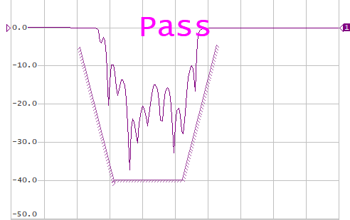
The result of the limit test is indicated in the center of the window:
•If the measurement result passed the limit test Pass sign will be displayed in green (See figure above).
•If the measurement result failed Fail sign will be displayed in red. The points of the trace, which failed the test will be highlighted in red (See figure below).
The fail sign can be disabled using the Fail Sign softkey.
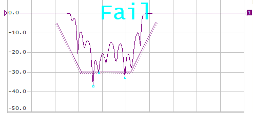
Test Fail Indication
Limit Test Enabling/Disabling
|
To enable/disable limit test function, use the following softkeys: Analysis > Limit Test > Limit Test [ON | OFF] |
|
|
Limit Test Display Management
|
To enable/disable display of a limit line, use the following softkeys: Analysis > Limit Test > Limit Line [ON | OFF] |
|
To enable/disable display of fail sign in the center of the diagram, use Fail Sign softkey. |
|
|
Limit Line Editing
In the editing mode the limit table will appear in the lower part of the screen (See figure below). The limit table will be hidden when quitting the submenu.
The Limit Line table fields can be edited directly in the table, just click on the field with the mouse and enter a new value.
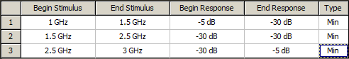
Limit Line Table
Navigating within the table to enter the values of the following parameters of a limit test segment:
Begin Stimulus |
Stimulus value in the beginning point of the segment. |
End Stimulus |
Stimulus value in the ending point of the segment. |
Begin Response |
Response value in the beginning point of the segment. |
End Response |
Response value in the ending point of the segment. |
Type |
Select the segment type among the following: •MAX — upper limit. •MIN — lower limit. •OFF — segment not used for the limit test. |
|
To access the limit line editing mode, use the following softkeys: Analysis > Limit Test > Edit Limit Line |
|
To add a new row in the table, click Add. The new row will appear below the highlighted one. To delete a row from the table, click Delete. The highlighted row will be deleted. |
|
To clear the entire table, use the Clear Limit Table softkey. |
|
To save the table into *.LIM file, use the Save Limit Table softkey. |
|
To open the table from a *.LIM file, use the Restore Limit Table softkey. |
|
|
Limit Line Offset
The limit line offset function allows the user to shift the segments of the limit line by the specified value along X and Y axes simultaneously.
|
To define the limit line offset along X-axis, use the following softkeys: Analysis > Limit Test > Limit Line Offsets > Stimulus Offset |
|
To define the limit line offset along Y-axis, use the following softkeys: Analysis > Limit Test > Limit Line Offsets > Response Offset |
|
|