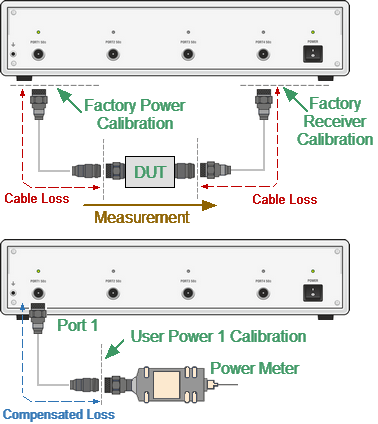
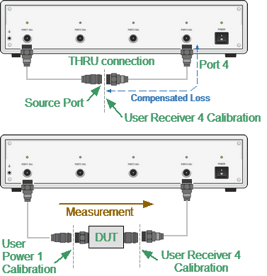
Receiver calibration is only used for absolute measurements. The receiver calibration is divided into the test receiver (T1, T2, T3, T4) calibration and the reference receiver (R1, R2, R3, R4) calibration (See Analyzer Block Diagram). The calibration procedure is different for these receivers.
1. Test receiver calibration
When performing absolute power measurements (See Absolute Measurements), the gain of receivers is factory calibrated to test port on the front panel.


Receiver Calibration
In practice, the power is measured at test port inputs made by the fixture producing losses. The test receiver calibration allows to measure the power at port inputs with higher accuracy.
The receiver calibration is performed by sending the calibration signal from the source port to the calibrated port input. The receiver calibration requires the connection between the both test ports using THRU connection.
To make the receiver calibration most accurate, first perform power calibration on the source port. If the source power calibration was not performed, the calibrated port needs to be connected to the source port on the front panel.
2. Reference receiver calibration
When performing a receiver calibration on a reference receiver, no connection is necessary as the receiver is internally connected to the source. That is why the source port number must be specified the same as the reference receiver port number.
An exception to this is the Analizer models with the direct receiver access, which allow you to connect a reference receiver to any source port. In this case, you must specify the actual source port number.
3. Power offset
It is possible to specify the power offset value before calibration. As a result, the receiver readings will be offset by this value.
4. General comments
After the receiver calibration is complete, receiver correction automatically turns on. Later it is possible to disable or enable again the receiver correction function.
The power calibration is performed for each port and each channel individually.
note |
The power correction status is indicated in the trace status field (See Trace Status Field) and in the channel status bar (See Channel Status Bar). |
Receiver Calibration Procedure
Connect a THRU between the test receiver port and the source port. In case of the Analyzer with the direct receiver access connect a THRU between the reference receiver connector and the source port.
|
To select the calibrated port number, use the following softkeys: Calibration > Receiver Calibration > Select Port |
|
To select the source port number, use the following softkeys: Calibration > Receiver Calibration > Source Port |
note |
If the reference receiver is being calibrated, the source port number must be the same as the receiver port number, except for Analyzers with direct access to the receiver. |
|
To set the power offset value when the receiver calibration is performed, use the following softkeys: Calibration > Receiver Calibration > Power Offset |
|
To execute the test receiver calibration, use the following softkeys: Calibration > Receiver Calibration > Calibrate Test Receiver To execute the reference receiver calibration, use the following softkeys: Calibration > Receiver Calibration > Calibrate Reference Receiver Use the Calibrate Both softkey to perform the calibration of the test and reference port receivers in succession. Note: Don't use this button if the test receiver and reference receiver require a different source port number. |
|
|
note |
After the receiver calibration is complete, receiver correction automatically turns on. |
Receiver Correction Setting
|
To enable/disable receiver correction, use the following softkeys: Calibration > Receiver Calibration > Correction |
|
|


