note |
The availability of this feature depends on the Analyzer model (See corresponding datasheet). |
The Analyzer measures parameters of the DUT in the frequency domain. Time domain transformation is a function of mathematical transformation of the measured parameters in order to obtain the time domain representation.
Time domain function simulates time-domain reflectometry. The meaning of which is to influence the DUT with a pulsed or step signal, followed by the analysis of the reflected signal. The magnitude, duration, and shape of the reflected signal determine the nature of the impedance variation in the DUT. The Analyzer does not affect the DUT either in pulses or steps. Instead, a Chirp-Z transform algorithm is used to calculate time information from the frequency measurements. The Chirp-Z transform is a generalization of the Fourier transform that allows to set arbitrary transform start and stop values.
Transformation Types
The time domain function supports the following transformation types:
•Bandpass mode simulates the response of the bandpass network to the impulse.
•Lowpass impulse mode simulates the response of the lowpass network to the impulse.
•Lowpass step mode simulates the response of the lowpass network to the unit step function.
The time domain resolution in the lowpass mode is twice as high as in the bandpass mode. The bandpass mode determines the distance to the discontinuity but does not provide information about the nature of the discontinuity. The lowpass mode determines the distance to the discontinuity and provides information about the nature of the discontinuity (open or short circuit, for example). The lowpass step mode is useful for the impedance measurement along the distance.
Bandpass mode is applied to the DUTs that do not operate with DC current such as band pass filters. The frequency settings in the bandpass mode can be arbitrary.
Lowpass mode is applied to the DUTs that operate with DC current such as cables.
The frequency settings in the lowpass mode is required to be a harmonic frequency grid, where the frequency value at each frequency point is an integer multiple of the start frequency. The Analyzer can set the harmonic frequency grid from the current frequency settings with one click.
The value of the DUT response at DC is required to be known in the lowpass mode. The DC value cannot be measured directly by the Analyzer. The Analyzer offers two options: the DC value is automatically extrapolated or manually set. The last option is used when the DUT response at DC is well known, for example, for a low loss cable the DC value is:
•"1" for open-ended cable.
•"-1" for a short-circuited cable.
•"0" for a cable terminated with a matched load.
Transformation Unambiguity Range
The time domain response is a periodic function due to the discrete nature of the frequency response. The time domain unambiguity range is determined by the step in the frequency domain:
;
Windowing
The time domain response has a ringing due to the finite nature of the frequency response. To reduce the ringing the windowing is applied to the frequency response. The time domain transformation function applies the Kaiser window function. The window function selection is a tradeoff between the ringing reducing and the time domain resolution.
The Kaiser window is defined by the β parameter, which smoothly fine-tunes the window shape from minimum (rectangular) to maximum. The user can fine-tune the window shape, or select one of the three pre-programmed windows:
•Minimum (rectangular)
•Normal
•Maximum
Pre-programmed window types
Window |
Lowpass Impulse |
Lowpass Step |
||
|---|---|---|---|---|
Side Lobes Level |
Pulse Width |
Side Lobes Level |
Edge Width |
|
Minimum |
– 13 dB |
|
– 21 dB |
|
Normal |
– 44 dB |
|
– 60 dB |
|
Maximum |
– 75 dB |
|
– 70 dB |
|
X-axis Representation
The X-axis units can be set in seconds or distance units (meters or feet). When the distance units are selected, the velocity factor is used to compute the distance from time. The velocity factor setting is located in the cable correction function (See Cable Correction Function).
The two types of reflection can be selected: round trip or one way. The round trip setting shows the total time or distance that the signal travels in both directions along the DUT. The one-way setting shows the time or distance the signal travels in one direction along the DUT.
note |
As the time domain transformation can be applied for separate traces of a channel, the x-axis units and round trip/one-way type depends on the active trace selected. |
The time domain transformation is applied for separate traces of a channel. The trace to which the function is applied must be preselected as active (See Selection of Active Trace/Channel).
Time Domain Transformation Activation
|
To enable/disable time domain transformation function, use the following softkeys: Analysis > Time Domain > Time Domain [ON | OFF] |
|
|
note |
Time domain transformation function is accessible only in linear frequency sweep mode. |
Time Domain Transformation Span
To define the span of time domain representation, its start and stop, or center and span values can be set.
|
To set the start and stop limits of the time domain range, use the following softkeys: Analysis > Time Domain > Start Analysis > Time Domain > Stop |
|
To set the center and span of the time domain, use the following softkeys: Analysis > Time Domain > Center Analysis > Time Domain > Span |
|
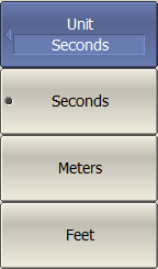
To set the unit of the time domain, use the following softkeys: Analysis > Time Domain > Unit > [ Seconds | Meters | Feet ] |
|
|
Time Domain Transformation Type
|
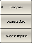
To set the time domain transformation type, use the following softkeys: Analysis > Time Domain > Type > [ Bandpass | Lowpass Impulse | Lowpass Step ] |
|
|
Time Domain Transformation Window Shape Setting
|
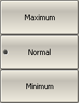
To set the window shape, use the following softkeys: Analysis > Time Domain > Window > [ Minimum | Normal | Maximum ] |
|
To set the window shape for the specific impulse width or front edge width, use the following softkeys: Analysis > Time Domain > Window > Impulse Width |
|
To set the window shape for the specific β-parameter of the Kaiser-Bessel filter, use the following softkeys: Analysis > Time Domain > Window > Kaiser Beta The available β values are from 0 to 13: •"0" corresponds to minimum window. •"6" corresponds to normal window. •"13" corresponds to maximum widow. |
|
|
note |
The impulse width and β of the Kaiser-Bessel filter are the dependent parameters. When setting one of the parameters the other one will be adjusted automatically. |
Cable Correction Settings
When the length units are selected the velocity factor setting of the Cable correction function affects the X-axis scale. See Cable Correction Function.
Lowpass Mode Settings
If lowpass mode is used, the frequency range must be set to a harmonic grid. The frequency values in measurement points are integer multiples of the start frequency.
In lowpass mode, the value of the DUT response at DC is extrapolated from the first few frequency points, or manually set. Set the DC value manually if the response of DUT is well known. For example, if the DUT is a cable then DC value is:
•"1" for open-ended cable.
•"-1" for a short-circuited cable.
•"0" for a cable terminated with a matched load.
|
To create a harmonic grid for the current frequency range, use the following softkeys: Analysis > Time Domain > Set Frequency Low Pass |
|
To turn on/off the automatic extrapolation of DC value, use the following softkeys: Analysis > Time Domain > Extrapolate DC [ ON | OFF ] |
|
To set the DC value manually, use the following softkeys: Analysis > Time Domain > DC Value |
|
|
note |
The Set Frequency Low Pass, Extrapolate DC, DC Value softkeys are duplicated in the Gating menu. The settings they make have the same effect on Time Domain and Gating. The Type (of time domain transformation) softkey is related to the DUT Low Pass softkey in the Gating menu as follows: •If Type set to Lowpass [ Impulse or Step ], DUT Low Pass turn ON. •If Type set to Bandpass, DUT Low Pass turn OFF. |


