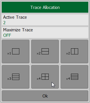
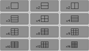
By default, traces are displayed overlapping one other in the diagram. If you wish to display the traces in separate diagrams, the number and layout of the diagrams can be set in the channel window as shown below.
Options for diagram placement in the channel for RVNA
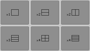
Options for diagram placement in the channel for RNVNA
Unlike channel windows, the number of traces and layout of the trace in diagrams are not related. The number of traces and the number of diagrams are set independently.
Placing traces in a diagram:
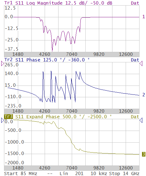
•If the number of traces and the number of diagrams are equal, all the traces will be displayed separately, each in an individual diagram.
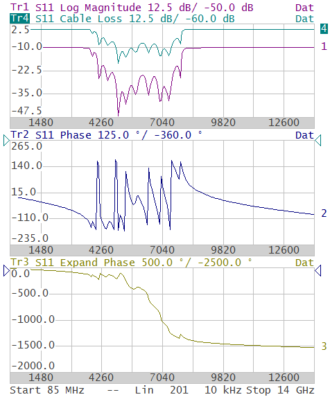
•If the number of traces is greater than the number of diagrams, traces will be assigned successively (beginning from the smallest trace number) to the number of available diagrams. When all diagrams are utilized, the process will continue from the first diagram (the following in succession traces will be added in diagrams).
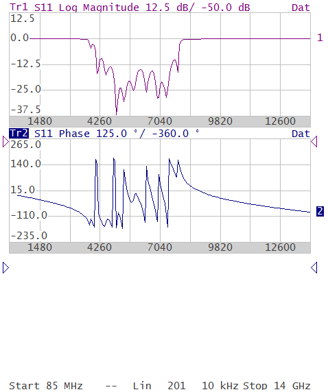
•If the number of traces is smaller than the number of diagrams, empty diagrams will be displayed.
If two or more traces are displayed in one diagram, the vertical scale will be shown for the active trace.
If two or more traces are displayed in one diagram, markers data will be shown for the active trace.
The stimulus axis is the same for all the traces of the channel, except when Time Domain Transformation is applied to some of the traces. In this case, the displayed stimulus axis will correspond to the active trace.
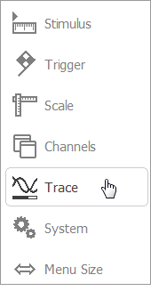
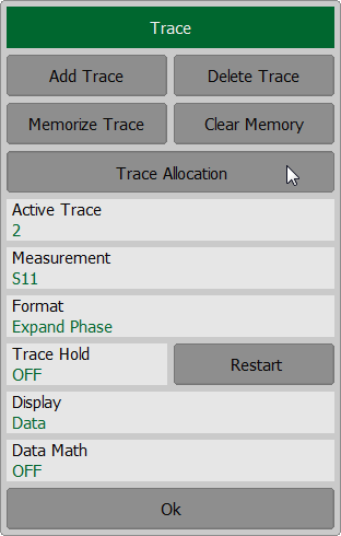
To allocate the traces in diagrams, use the following softkey in the right menu bar Trace > Trace Allocation.
Then select the softkey with the required number and layout of the channel windows. |