The Analyzer measures parameters of the DUT in the frequency domain. Time domain transformation is a function of mathematical transformation of the measured parameters in order to obtain the time domain representation. The functions are applicable for reflection coefficients (S11, S22 etc.) measurement only.
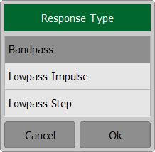
The time domain function allows to select the following transformation types:
•Bandpass mode simulates the response of the bandpass network to the impulse.
•Lowpass impulse mode simulates the response of the lowpass network to the impulse.
•Lowpass step mode simulates the response of the lowpass network to the unit step function.
Bandpass mode is applied to the DUTs that do not operate with DC current such as band pass filters. The frequency settings can be arbitrary.
Lowpass mode is applied to the DUTs that operate with DC current such as cables. The DC value is extrapolated from the first few frequency points; however a user has ability to set the DC value manually. The frequency settings are required to be a harmonic frequency grid, where the frequency value at each frequency point is an integer multiple of the start frequency.
The time domain resolution in the lowpass mode is twice as high as in the bandpass mode.
The time domain is a periodic function due to the discrete nature of the frequency response. The time domain ambiguity range is determined by the step in the frequency domain:
;
The time domain response has a ringing due to the finite nature of the frequency response. To reduce the ringing the windowing is applied to the frequency response. The time domain transformation function applies the Kaiser window function. The window function selection is a tradeoff between the ringing reducing and the time domain resolution.
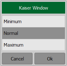
The Kaiser window is defined by the β parameter, which smoothly fine-tunes the window shape from minimum (rectangular) to maximum. The user can fine-tune the window shape, or select one of the three pre-programmed windows:
•Minimum (rectangular)
•Normal
•Maximum
Preprogrammed window types
Window |
Lowpass Impulse |
Lowpass Step |
||
|---|---|---|---|---|
Side Lobes Level |
Pulse Width (50 %) 1 |
Sidelobes Level |
Edge Width (10 – 90 %) |
|
Minimum |
– 13 dB |
|
– 21 dB |
|
Normal |
– 44 dB |
|
– 60 dB |
|
Maximum |
– 75 dB |
|
– 70 dB |
|
1 The value in the band pass mode is 2 times the value in the low pass mode. |
||||
note |
As the time domain transformation can be applied for separate traces of a channel, the stimulus axis label will be displayed depending on the active trace, in frequency or time units. |
Time Domain Transformation Activation
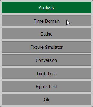
To enable/disable time domain transformation function, use the Analysis > Time Domain > Time Domain softkeys on left menu bar.
|

note |
Time domain transformation function is accessible only in linear frequency sweep mode. |
Time Domain Transformation Span
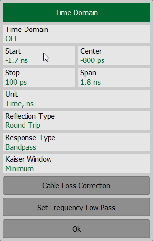
To define the span of time domain representation, its start and stop, or center and span values can be set.
If the velocity factor of the measured trace is known, for example in coaxial cable, the time intervals are recalculated into distances.
The transformation function allows setting of the measurement range in time domain within the limits of ambiguity range. The ambiguity range is determined by the measurement step in the frequency domain:
,
where — number of measurement points.
— stimulus start frequency.
— stimulus stop frequency.
The ambiguity range is recalculated into the maximum operating DTF (Distance to Fault) value:
,
where — velocity of light in vacuum;
— cable velocity factor.
The DTF maximum value can be increased by decreasing the frequency step.
For example, if start frequency is 300 MHz, stop frequency is 600 MHz, the number of points is 10001, and velocity factor is 1, then maximum distance to fault equals is to 4996.5 m, i.e. approximately 5 km.
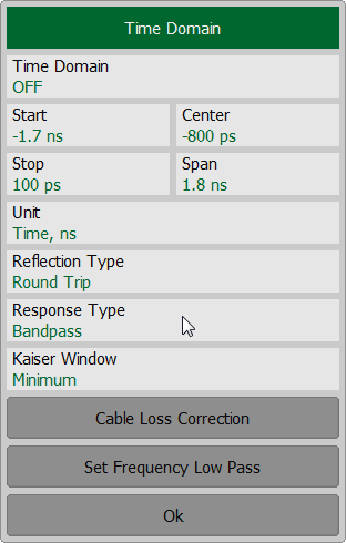
To set the start and stop limits of the time domain range, use the Analysis > Time Domain softkeys on left menu bar. Click on the Start or Stop field and enter the value using the on-screen keypad. To set the center and span of the time domain, use the Center or Span softkeys.
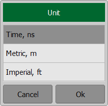
To set the unit of the time domain, click on Unit field and select the required type from the Unit list.
|
Time Domain Transformation Type
To set time domain transformation type, use the Analysis > Time Domain softkeys on left menu bar. Click on the Response Type field and select the required type from the Response Type list.
|
Time Domain Transformation Window Shape Setting
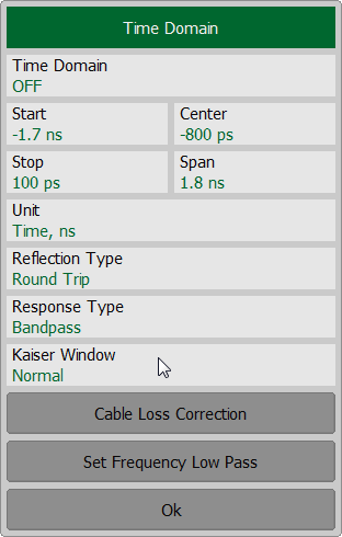
To set window shape, use the Analysis > Time Domain softkeys on left menu bar. Click on the Kaiser Window field and select the required type from the Response Type list.
|
Time Domain Transformation Reflection Type
To set window shape, use the Analysis > Time Domain softkeys on left menu bar. Click on the Reflection Type field to toggle setting between Round Trip or One way.
|

Cable Correction Setting
When the length units are selected the velocity factor setting of the Cable correction function affects the X-axis scale. See Cable Correction Function.
Frequency Harmonic Grid Setting
If lowpass mode is used, the frequency range must be set to a harmonic grid. The frequency values in measurement points are integer multiples of the start frequency Fmin.
To create a harmonic grid for the current frequency range, use the Analysis > Time Domain > Set Frequency Low Pass softkeys on left menu bar.
|
