The top panel view of the Analyzers is represented in the figures below.
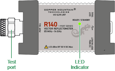
R140 top panel
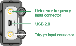
R140 side panel
Part of the R140
Test port
The test port (type-N male 50 Ω) is intended for DUT connection. It is also used as a source of the stimulus signal and as a receiver of the response signal from the DUT.
LED Indicator
The top panel is equipped with the READY/STANDBY LED indicator running in the following modes:
•Green blinking light is standby mode. In this mode the current consumption of the device from the USB port is minimum.
•Green glowing light is normal device operation.
USB Connector
The USB 2.0 port is intended for connection to USB port of the personal computer via the supplied USB cable.
Reference Frequency Input Connector
External reference frequency see in its specifications, input level is 2 dBm ± 2 dB, input impedance at «Ref In» is 50 Ω. Connector type is SMA female.
External Trigger Signal Input Connector
This connector allows the user to connect an external trigger source. Connector type is SMA female. TTL compatible inputs of 3 V to 5 V magnitude have up to 1 us pulse width. Input impedance is at least 10 kΩ.