The top panel view of the Analyzers is represented in the figures below.
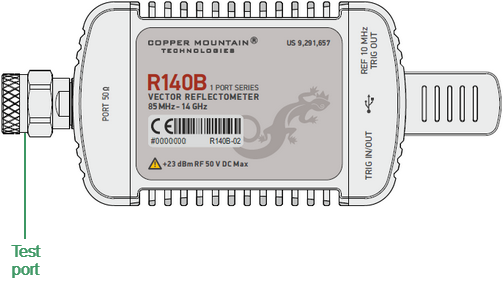
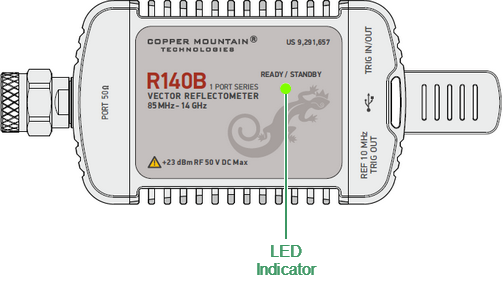
R140B top panel
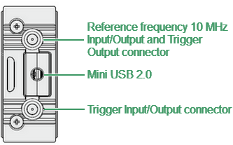
R140B rear panel
R140B side panel
Part of the R140B
Test port
The test port is intended for DUT connection. The test port is type-N 50 Ω or 3.5 mm (See Hardware configurations). It is also used as a source of the stimulus signal and as a receiver of the response signal from the DUT.
LED Indicator
The top panel is equipped with the READY/STANDBY LED indicator running in the following modes:
•Green blinking light is standby mode. In this mode the current consumption of the device from the USB port is minimum.
•Green glowing light is normal device operation.
USB Connector
The USB 2.0 port is intended for connection to USB port of the personal computer via the supplied USB cable.
Reference Frequency Input/Output or External Trigger Signal Output Connector
The user can use the port as a reference frequency input/output or as an external trigger signal output. Connector type is SMA female.
External reference frequency is 10 MHz, input level is 2 dBm ± 2 dB, input impedance is 50 Ohm. Output reference signal level is 3 dBm ± 2 dB into 50 Ohm impedance.
The external trigger signal output port can be used to provide trigger to an external device. The port outputs various waveforms depending on the setting of the Output Trigger Function: before frequency setup pulse, before sampling pulse, after sampling pulse, ready for external trigger, end of sweep pulse, measurement sweep. In this case, the External Trigger Signal Input/Output port is used as an input of an external trigger source.
External Trigger Signal Input/Output Connector
The user can use the port as an external trigger signal output or input. Connector type is SMA female.
External Trigger Signal Input allows the user to connect an external trigger source. Connector type is SMA female. 3.3v CMOS TTL compatible inputs magnitude have at least 1 μs pulse width. Input impedance is at least 10 kOhm. The External Trigger Signal Output port can be used to provide trigger to an external device. The port outputs various waveforms depending on the setting of the Output Trigger Function: before frequency setup pulse, before sampling pulse, after sampling pulse, ready for external trigger, end of sweep pulse, measurement sweep.
Hardware configurations
Model |
Connector type |
|---|---|
R140B-01 |
Type-N, female |
R140B-02 |
Type-N, male |
R140B-11 |
3.5 mm, female |
R140B-12 |
3.5 mm, male |