Adapter Removal and Adapter Insertion functions are designed to mathematically exclude adapter characteristics from the calibration plane or add adapter characteristics to the calibration plane. They adapt two-port SOLT calibration with Zero-Length Thru for non-insertable device measurement. Functions are performed in two steps. The first step is performing two-port SOLT calibration, the second is measuring 3 standards Short-Open-Load to exclude/include adapter.
The parameters of the adapter do not need to be known. Requirements for the adapter are the same as for UNKNOWN THRU. For a detailed description, see Unknown Thru Requirements. For a typical adapter-transition between different types of connectors, these requirements are easily met.
Adapter Removal Function
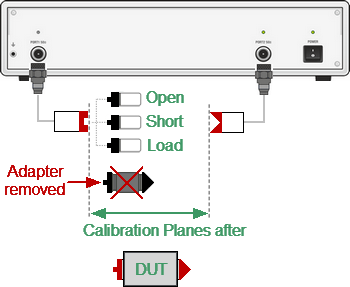
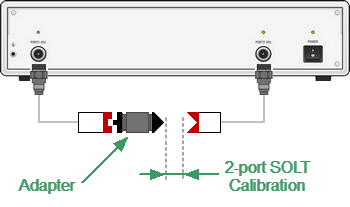
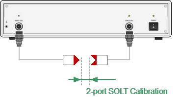
Adapter Removal function used to remove any adapter characteristics from the calibration plane. The function is used when, for two-port SOLT calibration, the connection of zero length thru test port cables is only possible with an adapter. Adapter is added to measuring setup, two-port SOLT calibration is performed. After the calibration is complete, the adapter is removed from the measuring setup. Adapter characteristics are mathematically removed from the calibration plane using three Open-Short-Load standards (See figure below).
First Stage of Adapter removal function

Second Stage of Adapter removal function
Adapter Removal procedure (See Adapter removal figure):
•Connect the adapter to the port.
•Perform two-port SOLT calibration.
•Remove the adapter.
•In Adapter Removal/Insertion submenu select port number to which the adapter was connected.
•Set Adapter Delay (Adapter Length) or leave it at zero to automatically detect it. If the Adapter type is waveguide, set its type and Cutoff Frequency.
•Measure three standards: OPEN, SHORT, and LOAD, for the corresponding test port.
•To complete the Adapter Remove procedure, click Apply.
Adapter Insertion function
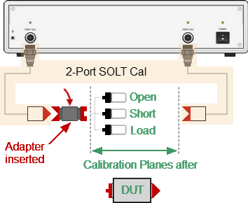
Adapter Insertion function used to insert any adapter characteristics to the calibration plane. The function is used when test port cables allow connection zero-length thru, but it is possible to connect DUT to them only with the use of an adapter. 2-port SOLT calibration is performed. After the calibration is complete, the adapter is added to the measuring setup. Adapter characteristics are mathematically added to the calibration plane using three Open-Short-Load standards (See figure below).
First Stage of Adapter insertion function

Second Stage of Adapter insertion
Adapter Insertion procedure (see Adapter insertion figure):
•Perform two-port SOLT calibration.
•Connect the adapter to the test port, which cannot be directly connected to the DUT.
•In Adapter Removal/Insertion submenu select the port number to which the adapter is connected.
•Set Adapter Delay (Adapter Length) or leave it at zero to automatically detect it. If the Adapter type is waveguide, set its type and Cutoff Frequency.
•Measure three standards: OPEN, SHORT, and LOAD, for the corresponding test port.
•To complete the Adapter Insert procedure, click Apply.
note |
The Adapter Removal/Insertion function is accessible when the status of the initial two-port calibration is [Cor], not [С?] or [C!]. |
note |
Before starting adapter removal, select the appropriate calibration kit. |
note |
When test ports have different Z0, enable automatic Z0 selecting function (See Automatic Z0 Selecting). |
|
|
To open the Adapter Removal/Insertion submenu, use the following softkeys: Calibration > Calibrate > Adapter Removal |
|
|
Select the port number for Adapter Removal/Insertion using Select Port. |
|
|
Enter the adapter delay or length or set 0 for AUTO using Adapter Delay. |
|
|
Select the Adapter media: coax or waveguide using Adapter Media. |
|
|
Select the desired measurement units for delay (length): seconds or meters using Delay Unit. |
|
|
When the measurement units Meters are selected, enter the permittivity value using Permittivity. |
|
|
When the adapter media Waveguide is selected, enter the Cutoff Frequency value using Cutoff Frequency. |
|
|
Connect SHORT, OPEN, and LOAD standards to the selected port in any consequence as shown in Full One-Port Calibration. Perform measurements clicking the softkey corresponding to the connected standard. The instrument status bar will indicate Calibration in progress... when the measurement is in progress. On completion of the measurement, a check mark will appear in the left part of the softkey. |
|
|
To complete the Adapter Remove/Insert procedure, click Apply. |
|
|
To clear the measurement results of the standard, click Cancel. This softkey does not cancel the current calibration. To disable the current calibration, turn off the error correction function (See Error Correction Disabling). |


