The rear view of the Analyzers is represented in the figures below.
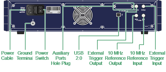
C1409, C2409 rear panel
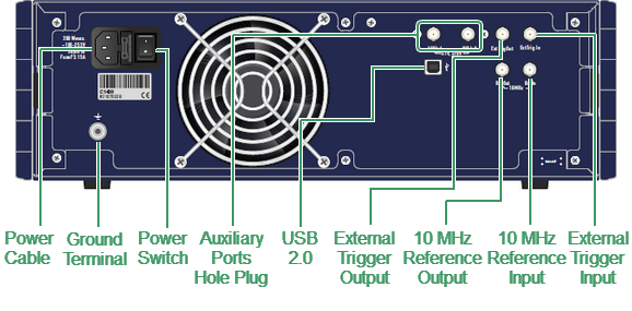
C1420, C2420 rear panel
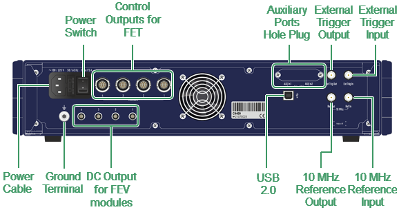
C4409 rear panel
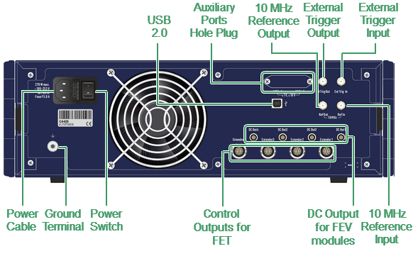
C4420 rear panel
Part of rear panel
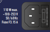
Power Cable Receptacle
|
The power cable receptacle is intended for 100 VAC to 253 VAC 50/60 Hz power cable connection. The cable receptacle has a built-in switch and fuse holder. The power switch serves as the disconnecting device (device that cuts off power supply) of the VNA. The power supply must be cut off to avoid such danger is electric shock, during prolonged non-use of the device. A Fuse protects the Analyzer from the excessive current. |
External Trigger Signal Input Connector
|
This connector allows for the connection of an external trigger source. Connector type is BNC female. For input and signal parameters, see instrument specification. |

External Trigger Signal Output Connector
|
The External Trigger Signal Output port can be used to provide trigger to an external device. The port outputs signal with various waveforms depending on the setting of the Output Trigger Function: before frequency setup pulse, before sampling pulse, after sampling pulse, ready for external trigger, end of sweep pulse, measurement sweep. |

Internal Reference Frequency Output Connector
|
External reference frequency is 10 MHz, input level is 2 dBm ± 2 dB, input impedance at «Ref In» is 50 Ω. Connector type is BNC female. |

External Reference Frequency Input Connector
|
Input reference signal level is 3 dBm ± 2 dB at 50 Ω impedance. Connector type is BNC female. |

USB 2.0 High Speed Port
|
The USB port is intended for connection to an external PC. |

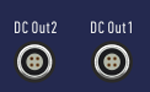
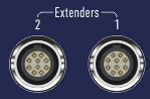
Power and Control Connectors for Frequency Extension System (C4409, C4420 only)
|
External frequency extenders are powered by a DC voltage from the analyzer power supply. DC Out connectors are used for powering FEV frequency extension modules. Extender connectors are used for powering and controlling FET frequency extension modules. These connectors include power and control lines. |
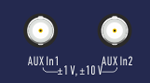
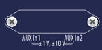
Auxiliary Input Ports (HW-C-AUX option for Cobalt series)
|
A two-channel DC voltmeter board can be optionally included in the Analyzer. A DC voltmeter measures voltage synchronously with the sweeping frequency when measuring S-parameters. Two additional ports AUX in1 and AUX in2 are voltmeter inputs. The hole for the connectors is closed with a plug if the option is not present. |
Ground Terminal
|
To avoid electric shock, use this terminal for grounding. The Ground terminal allows to connect directly the body of the Analyzer to the test station ground in order to ensure electrical safety. |
