This is a series of rack-mounted VNAs - a series that delivers industry-leading dynamic range and sweep speed, with all the features engineers have come to expect included standard in our software. This series also includes analyzers that are compatible with frequency extenders or have direct access to receivers. The Auxiliary Board Option is available on all Cobalt VNAs at the time of order (factory-installed) or as an add-on at a later date.
The front view of the Analyzers is represented in the figures below.
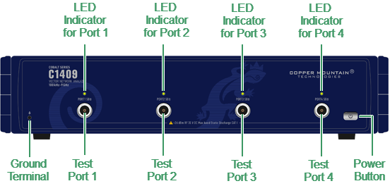
C1409 front panel
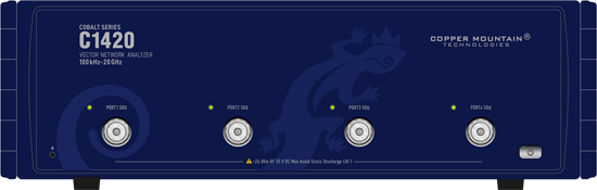
C1420 front panel
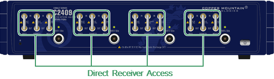
C2409 front panel

C2420 front panel
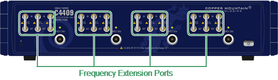
C4409 front panel
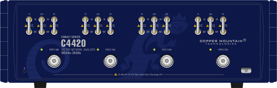
C4420 front panel
Part of front panel
Power Button
|
Switches the Analyzer ON and OFF. The analyzer can be turned on/off at any time. The VNA loads its operating firmware from the PC each time upon powering up. The process will take approximately 10 seconds, after which the Analyzer will be ready for operation. |

note |
The USB driver will be installed onto the PC when the analyzer is turned on for the first time. The driver installation procedure is described in Software Installation. Some PCs may require re-installation of the driver in case of change of the USB port. |
Test Ports


note |
The LED indicator identifies the test port which is operating as a signal source. |
Caution |
Do not exceed the maximum allowed power of the input RF signal (or maximum DC voltage) indicated on the front panel. This may lead to damage of the Analyzer. |
Ground Terminal
|
Use the terminal for grounding. To avoid damage from electric discharge, connect the ground terminal on the body of the Analyzer to a reliable earth ground shared with the DUT in the test environment. |

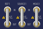
Adjustable Ports Configurations (C2409, C2420 models only)
|
Adjustable port configurations with direct access to the receivers of the VNA provide for a variety of test applications requiring wider dynamic and power range. Direct receiver access enables testing of high power devices. Additional amplifiers, attenuators, various filters and matching pads for each of the ports may be introduced in reference oscillator and receiver path to ensure optimal operation of the receivers. |
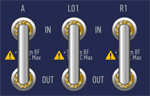
Additional Ports for Frequency Extension System (C4409, C4420 models only)
|
C4409, C4420 analyzers have additional ports on the front panel for connecting frequency extension system. The signal from the analyzer's local oscillator (LO1 output) is supplied to the frequency extension system. Signals from the extension system are fed to the inputs of the test and reference receivers of the analyzer (T1 in and R1 in). Unless frequency extension system is used, each pair of ports is connected with a jumper cable assembly. |