The Vector Network Analyzer (VNA) is a tool for accurate measurement of complex transmission and reflection coefficients (S-parameters) of a Device Under Test (DUT).
The Analyzers described in this manual are USB VNAs. These VNAs consist of an RF measurement module (Analyzer) and supplied processing software — an application which runs on a Windows or Linux based PC or laptop, connected to the Analyzer’s hardware via a USB interface. This application controls the RF measurement module, receives and post-processes received raw data and presents the calibrated results to the user in a variety of graphical formats.
The Analyzers described in this manual differ in such parameters as frequency range, output power, measurement speed, dynamic range, and measurement accuracy. Direct access to receivers and the possibility of connecting frequency extension modules significantly affects the design and functions of the Analyzer.
For a detailed description of different series and models of Analyzers see Instrument Series.
The complete specification and supported features list are given in the datasheet of the corresponding Analyzer.
The block diagram of the Analyzer is represented in the following figure.
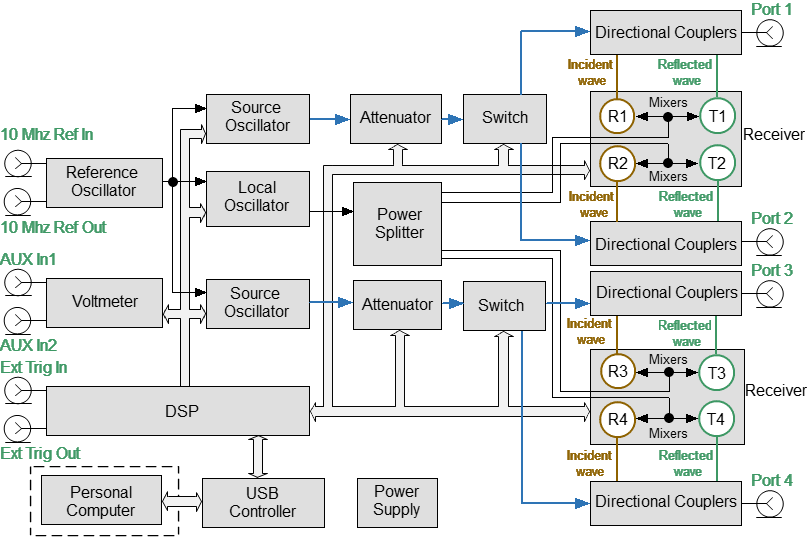
The block diagram of the Analyzer
The Analyzer consists of the following functional blocks: a Reference Oscillator, two Source Oscillators, a Local Oscillator, two power control Attenuators, two Switches, a Power Splitter, four Dual Directional Couplers, an eight-channel Receiver (depicted as two four-channel), a digital signal processor (DSP), and a Power Supply.
The structure of a four-port Analyzer consists of two similar parts, each of which is similar to a two-port Analyzer.
The test signal sources are two tunable Source Oscillators, each for its own pair of measurement ports. Source Oscillator design is based on digital frequency synthesizers. An internal Reference Oscillator provides the source oscillators with a stable reference signal. The presence of two independent Source Oscillators allows one of them to be used as an Auxiliary Source.
The Local Oscillator (LO) generates signals using digital frequency synthesizers at an offset from the Source Oscillator which is equal to the Intermediate Frequency (IF) which will be digitized by the VNA IF circuit.
The Local Oscillator is the source of the LO signal for the Receiver.
The Power Splitter distributes the LO signal between the eight Receivers.
The programmable Attenuators control the power level of the test signal, each in its own pair of measurement ports. These Attenuators are executive units of the automatic power control system. For example, when a power calibration has been completed, the Power Correction function uses these Attenuators. Also, the Analyzer can sweep over the output power range at a fixed frequency of test signal using these Attenuators. The Attenuators are controlled by setting the signal power level at the output of the measurement ports. The range of signal power levels is specified at the output for power sweep mode.
Switches, each for its own pair of measurement ports, change the direction of the test signal through the DUT, switching the Source Oscillator signal between the two Directional Couplers. Thus, any port can be the source or receiver of a signal. All the S-parameters can be measured by making only one DUT connection.
Directional Couplers separate the incident wave and reflected waves of signal transmitted through a DUT.
The incident and reflected signals from the four Directional Couplers are applied to a multi-channel Receiver. The multi-channel Receiver of the four-port Analyzer consists of eight identical channels (two channels per port). The reference receiver processes the incident wave, a measuring receiver processes the reflected wave. The Reference receiver is indicated as R with the index corresponding to the port number. The measuring receiver is indicated as T with the port index. Receiver Mixers convert the signal to an IF frequency. Analog-to-digital converters in a multi-channel receiver convert these IF signals to a sequence of digital samples and supply them to DSP. The DSP performs primary signal processing (filtering, phase difference estimation, magnitude measurement). The user selected IF Bandwidth is applied by the DSP filter.
After the primary signal processing, the DSP transmits the information to the control software running on an external PC. Communication is provided by a USB controller. This software applies calibration and performs the final calculations and displays the measurement results on the screen of PC. The software also controls the operation of the hardware of the Analyzer.
Adjustable port configuration with direct access to the receivers
Cobalt C2409, and C2420 Analyzer models allow direct access to the measurement receivers (See Figure below). This feature is intended for a variety of measurement applications requiring a wider dynamic and power range. Direct receiver access enables testing of high power devices. Additional amplifiers, attenuators, various filters, and matching pads for each of the ports can be introduced in the reference oscillator and receiver paths to ensure optimal operation of the receivers.
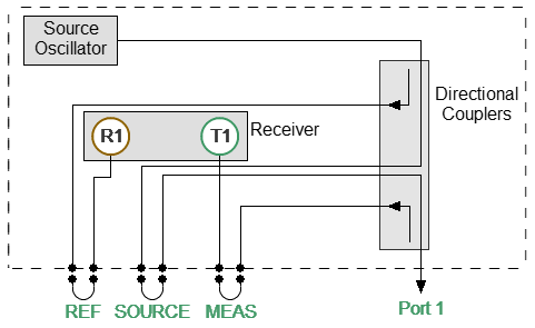
Direct access to receivers
Frequency extension system module connection
Cobalt C4409 and C4420 Analyzer models have additional ports with jumper cable assemblies on the configurable front panel for connecting Frequency Extension Modules (See figure below).
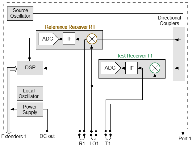
Frequency extension system
The Frequency Extension Modules, equipped with coaxial or waveguide connectors, are intended to extend the measurement frequency range from 18 to 110 GHz. The Analyzer provides power and control for Frequency Extension Modules. The power and control connectors for operating with Frequency Extension Modules are located on the rear panel of the Analyzer. The connection diagram is shown below.
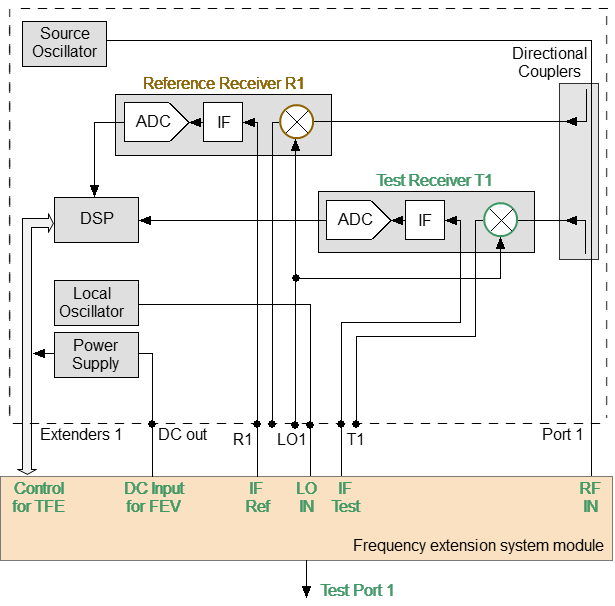
Frequency extension system module connection