The output power levels of the test and LO signals are set using the Analyzer software. The insertion loss of the RF and LO cables used is also specified in the software. Settings will be available after selecting the Module model in the frequency extender menu.
|
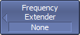
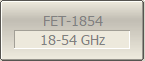
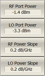
Select the required Module in the frequency extender menu (for example, FET1854): System > Misc Setup > Frequency extender > FET-1854 Settings the test and LO signal output power levels, and RF and/or LO cables insertion losses, will be available: •RF Port Power — test signal output power level. •LO Port Power — LO signal output power level. •RF Power Slope — RF cable insertion loss. •LO Power Slope — LO cable insertion loss. |
|
|
note |
If the Module is connected using RF and LO cables those indicated in the measurement system, the following values are recommended:
|
note |
If the Module is connected using RF and LO cables other than those indicated in the measurement system, make sure that the test and LO signal output power level at the Module input were in the ranges:
|
|
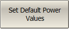
To set default parameters. use the following softkeys: System > Misc Setup > Frequency extender > Set Default Power Values |
note |
Use the status indicator on the rear panel to check the Module connection status. |